
 WhatsApp: +86 16626708626
 Email:
  Phone: +86 16626708626
Description
3. Key Technical Specifications
| Parameter | Value |
|---|---|
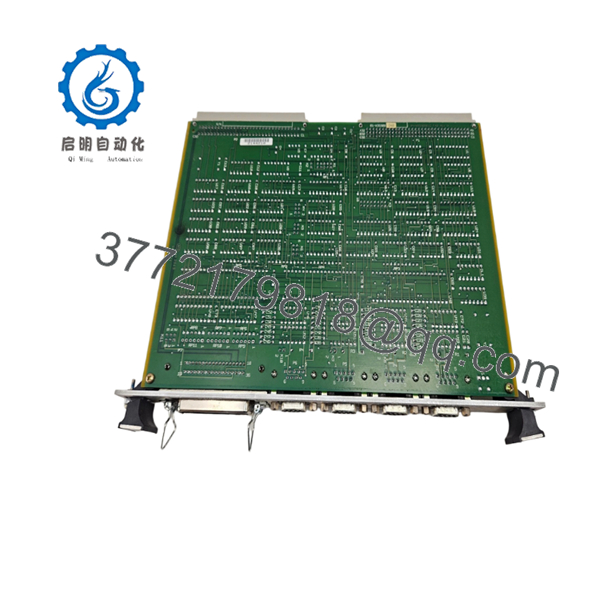
| Model | MVME335 |
| Manufacturer | Motorola |
| Product Type | Serial & Parallel Interface Board |
| Bus Interface | VMEbus |
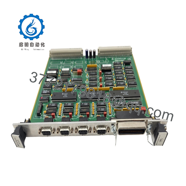
| Serial Channels | 4 Asynchronous Serial Ports |
| Serial Standard | RS-232C |
| Parallel Interface | 1 Centronics-Compatible Printer Port |
| Timer Resources | One 24-bit Timer and Two 16-bit Timers |
| Interrupt Support | Configurable Interrupt Levels |
| Installation Format | VMEbus Plug-In Module |
| Rear Transition Board | Compatible with MVME715P Transition Board |
| Typical Applications | Terminal Communications, PLC Connectivity, Printer Interface |
| Product Status | Obsolete Legacy Hardware |
The MVME335 provides four asynchronous serial communication channels and one parallel printer interface. The module was designed for industrial VME systems requiring multiple RS-232 communication ports for terminals, PLCs, analyzers, barcode systems, and supervisory control equipment. It also includes onboard timer resources for interrupt generation and communication management.
4. Product Introduction
The Motorola MVME335 is a VMEbus serial and parallel communication interface module used in legacy industrial automation, process control, telecommunications, and OEM embedded systems. Rather than performing CPU functions, the board expands system connectivity by providing four RS-232 serial channels and a Centronics-compatible parallel interface.
In field installations, the MVME335 commonly appears alongside Motorola MVME processor boards where reliable serial communication is required for HMIs, operator terminals, printers, instrumentation, and external controllers. For facilities maintaining legacy VME architectures, replacing a failed MVME335 is often considerably less expensive than redesigning the entire communication subsystem.
- MVME335
- MVME335
5. Installation & Configuration Guide
Stage 1: Pre-Installation Preparation (10 Minutes)
⚠️ Safety First
- Notify operations personnel of planned downtime.
- Place connected equipment in a safe state.
- Apply Lock-Out/Tag-Out procedures.
- Remove power from the VME chassis.
- Wait at least 5 minutes for capacitor discharge.
Tools Required
- ESD wrist strap
- PH1 screwdriver
- Fluke 115 multimeter
- Wire labels
- Smartphone camera
- Flashlight
Data Backup
- Document serial port assignments.
- Record communication parameters:
- Baud rate
- Data bits
- Parity
- Stop bits
- Photograph:
- Jumper settings
- Slot location
- Cable connections
- Transition board wiring
- Record interrupt assignments if configured.
Stage 2: Removing the Old Module (5 Minutes)
- Remove front-panel retaining screws.
- Label all communication cables.
- Disconnect rear transition-board connections.
- Release ejector handles.
- Pull the board straight out.
⚠️ Do not twist the board during extraction. VME connector damage frequently causes intermittent communication failures.
- Inspect:
- P1 connector
- P2 connector
- Backplane contacts
- Guide rails
⚠️ Keep the original module available until full communication testing is complete.
Stage 3: Installing the New Module (5 Minutes)
Configuration Clone (Critical)
- Connect ESD protection.
- Verify:
- MVME335 model number
- Assembly number
- Hardware revision
- Duplicate all jumper settings exactly.
According to Motorola service documentation, jumper settings control interrupt assignments, base addressing, DSR handling, and grounding configurations.
❗ This is the most common rookie mistake, but it happens constantly. Take a picture before you pull it. I can’t stress this enough.
- Insert the board evenly into the VME card guides.
- Seat connectors fully.
- Secure ejector handles.
- Reconnect serial and printer cables.
Self-Checklist
- Model verified
- Jumpers duplicated
- Connectors seated
- Cables secured
- Slot location verified
Stage 4: Power-On & Testing (10 Minutes)
Pre-Power Check
- Verify chassis grounding.
- Check power rails for shorts.
- Inspect serial cable integrity.
Power-On Steps
- Power the VME chassis.
- Verify CPU startup.
- Confirm VMEbus recognition.
- Connect engineering workstation.
- Verify serial communication operation.
- Test printer interface if installed.
Functional Testing
- Loopback-test each serial channel.
- Verify baud-rate configuration.
- Test interrupt operation.
- Verify printer communication.
- Run communication traffic for at least 30 minutes.
⚠️ Troubleshooting Note:
- No communication usually indicates incorrect jumper settings.
- Intermittent data errors often result from RS-232 cable grounding issues.
- Printer failures frequently trace back to transition-board wiring rather than the MVME335 itself.
Technical Pitfall & Survival Guide
❗ Firmware Revision and Driver Compatibility
I’ve seen maintenance teams replace a communication card and immediately blame the hardware when serial ports stopped responding.
The real problem was a driver mismatch inside the operating system.
Avoidance:
- Record software versions before shutdown.
- Verify supported drivers.
- Confirm interrupt assignments.
❗ Jumper Configuration Errors
The MVME335 relies heavily on jumper settings for interrupts and addressing. Motorola’s field service guide documents multiple configurable headers.
A single incorrect jumper can make all four ports appear dead.
Avoidance:
- Photograph every jumper.
- Compare boards side-by-side.
- Verify interrupt-level assignments.
❗ Transition Board Wiring Issues
Many installations use an MVME715P transition board for field wiring. Problems often originate there, not on the communication card itself.
Avoidance:
- Inspect transition-board connectors.
- Verify pin assignments.
- Check cable continuity.
❗ RS-232 Grounding Problems
Serial communications can appear healthy during commissioning but fail intermittently under plant conditions.
I’ve seen engineers spend hours troubleshooting software only to discover a floating shield connection.
Avoidance:
- Verify signal grounds.
- Follow site grounding standards.
- Check shield termination practices.
❗ Electrostatic Discharge (ESD)
I once watched a technician swap a serial card during winter without wearing a wrist strap.
The board powered up normally, then one communication channel failed several hours later.
Avoidance:
- Wear a grounded wrist strap.
- Use an ESD mat.
- Store boards in anti-static packaging.
Keep these checks in mind and you’ll save yourself 90% of typical rework time.
6. Frequently Asked Questions (FAQ)
Q1. What does the MVME335 actually do?
The MVME335 is a VMEbus communication interface module that provides four RS-232 serial channels and one parallel printer interface. It is not a CPU board.
Q2. Is the MVME335 obsolete?
Yes.
The MVME335 belongs to Motorola’s legacy VMEbus product family and has been out of production for many years. Most available inventory comes from surplus stock, refurbished equipment, or decommissioned systems.
Q3. Can I hot-swap the MVME335?
No.
Most VMEbus systems using the MVME335 were not designed for hot insertion. Removing the module under power can disrupt bus operation and potentially damage hardware.
Q4. What devices can connect to the serial ports?
Typical field applications include:
- Operator terminals
- PLCs
- DCS controllers
- Barcode readers
- Weighing systems
- Industrial analyzers
- SCADA communication equipment
The serial ports operate at RS-232C voltage levels.
Q5. What is the parallel port used for?
The parallel interface supports Centronics-type printer connections and other compatible parallel devices through the appropriate transition-board configuration.
Q6. Why do communication problems appear after replacing a working module?
In my experience, jumper settings cause more issues than hardware failures.
Most replacement problems involve:
- Interrupt conflicts
- Address mismatches
- Incorrect serial settings
- Transition-board wiring errors
Not defective hardware.
Q7. Why are surplus MVME335 boards still purchased today?
Because many industrial systems still depend on validated VME architectures. Replacing a communication board is usually far less expensive than migrating an entire control platform and requalifying software.
Quality Control & Verification Process
1. Inbound Inspection & Traceability
- Verify Motorola labels and assembly numbers.
- Confirm serial traceability.
- Inspect for:
- Corrosion
- Connector wear
- Rework marks
- UV discoloration
- Audit accessory completeness.
2. Live Functional Testing
- Install in a known-good VME test chassis.
- Verify system recognition.
- Test all four RS-232 channels.
- Verify parallel-port functionality.
- Execute timer and interrupt tests.
- Run continuous communication testing for 24+ hours.
- Generate a documented test report.
3. Electrical Parameter Testing
- 500 V insulation resistance test (>10 MΩ target).
- Ground continuity verification.
- Connector integrity inspection.
- Power consumption verification.
4. Firmware & Configuration Verification
- Document jumper positions.
- Photograph board configuration.
- Record interrupt settings.
- Archive test results.
5. Final QC & Packaging
- QC inspector sign-off.
- Anti-static ESD packaging.
- Bubble-wrap protection.
- Heavy-duty corrugated carton.
- QC Passed label with inspection date.
Test photos and communication test videos should be available upon request. The goal is not to claim failure-proof operation; it is to verify that every serial channel, interrupt function, and communication interface operates correctly under controlled load testing before shipment.


