WhatsApp: +86 16626708626
 Email:
 Phone: +86 16626708626
Description
Key Technical Specifications
| Parameter | Value |
|---|---|
| Processor | Motorola MPC750 PowerPC at 450 MHz (MVME5100 also fielded with MPC755 and MPC7410 variants) |
| L1 Cache | 32 KB instruction / 32 KB data (on-chip) |
| L2 Cache | 1 MB secondary backside cache (up to 2 MB on MPC7410 models) |
| Front-Side Bus | 100 MHz processor/memory bus |
| Memory Controller | Motorola Hawk memory/PCI controller ASIC (PowerPlus II architecture) |
| DRAM | 512 MB onboard ECC SDRAM; expandable to 1 GB with RAM500 mezzanine modules (2 × 256 MB stackable) |
| Flash Memory | 17 MB total (16 MB + 1 MB banks on X-Bus) |
| NVRAM / RTC | Battery-backed NVRAM with real-time clock |
| VMEbus Interface | Universe II VME64x PCI-to-VME bridge ASIC; master/slave, A32/D64 |
| PCI Bus | 64-bit / 33 MHz local PCI bus |
| PMC Expansion | Two IEEE P1386.1-compatible 32/64-bit PMC sites; 64-bit PCI expansion mezzanine connector (PMCspan) allowing up to four more PMCs |
| Ethernet | Dual 10/100 Mbps Ethernet (Intel 82559ER controllers), RJ-45 front panel |
| Serial Ports | Two 16550-compatible UART serial ports (COM1, COM2 front panel) |
| Rear I/O | P2 supports MVME761/712M transition module or IPMC761/IPMC712 mezzanine modes |
| Handles | IEEE handles (“-0163” designation; “-0161” uses Scanbe handles) |
| Temperature Rating | Extended temperature model (“5E” designator) — verify the precise operating range against the MVME5100 datasheet for your configuration |
| Power Requirements | ‘+5 V and +12 V from VME backplane (+12 V at 3.0 A typical; excludes PMC/IPMC module draw) |
| Form Factor | Single-slot 6U VME64x, double-height |
| Operating Systems | VxWorks, pSOS, Linux, AIX-derived RTOS environments; PPCBug firmware/debugger |
| Firmware | Motorola PPCBug with diagnostics |
⚠️ Configuration note: The suffix matters on this family. “5E” marks the extended temperature build; “-016x” means 512 MB ECC SDRAM with the MPC750 at 450 MHz; “-013x” is the 64 MB version. The sibling MVME51105E-2161 uses the MPC7410 with AltiVec at 400 MHz with 2 MB L2. These are not interchangeable without firmware and OS work. Verify the exact suffix against your installed board and the OEM datasheet before ordering.
Product Introduction
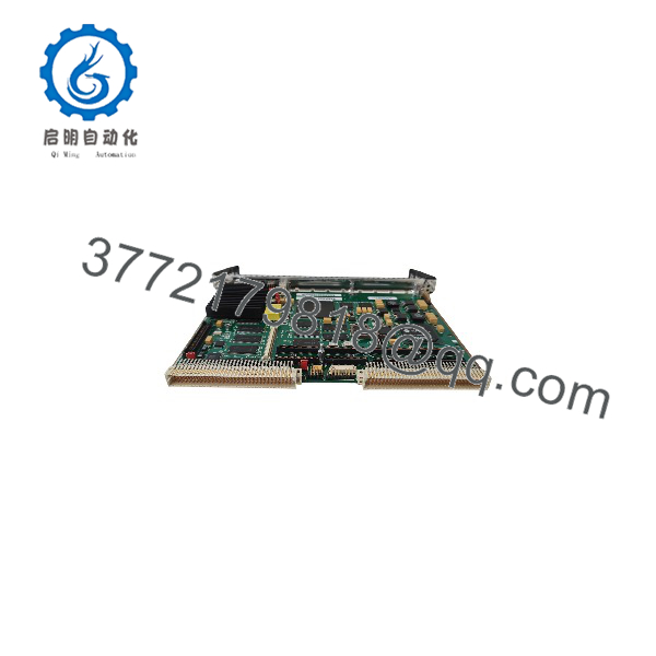
The Motorola MVME51005E-0163 is a single-slot VME64x single-board computer built on Motorola’s PowerPlus II architecture, pairing a 450 MHz MPC750 PowerPC processor with the Hawk memory controller, 512 MB of ECC SDRAM, and 17 MB of Flash. The “5E” build is the extended temperature variant, aimed at industrial, defense, and transportation applications where cabinet climate control can’t be guaranteed.
The board’s strength is balance: a 100 MHz front-side bus feeding ECC memory, dual 10/100 Ethernet ports, two PMC sites, and the Universe II VME64x bridge on a clean 64-bit PCI segment. It also supports legacy MVME761/MVME712M transition modules and IPMC mezzanines, which means an MVME2600/2700-era chassis can be processor-refreshed without rewiring the backplane. That compatibility is why the MVME5100 became the standard mid-tier VME workhorse — and why plants still source it two decades later.
MVME51005E-0163
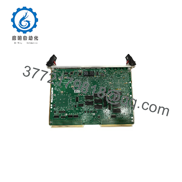
MVME51005E-0163
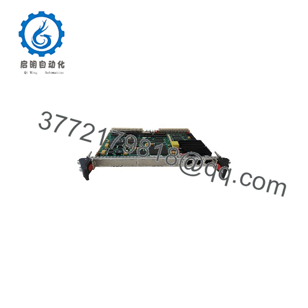
MVME51005E-0163
Installation & Configuration Guide
Realistic time budget: 45–60 minutes for a like-for-like swap plus application reload. Budget extra time if PMC or IPMC mezzanines are installed.
Stage 1: Pre-Installation Preparation (10–15 min)
- ⚠️ Safety First: Notify operations of the downtime window. Drive the process to a safe state. Lock out/tag out chassis power. Wait 5 minutes for backplane capacitor discharge.
- Tools Required: Grounded ESD wrist strap, ESD mat, flat-blade screwdriver for injector/ejector screws, Fluke 115-class multimeter, cable labels, smartphone for photos.
- Data Backup — do it while the old board still boots:
- Photograph the front panel, Ethernet/serial cabling, PMC site occupants, and any configuration stickers.
- Record the PPCBug firmware version and dump the environment variables (ENV/CNFG) over the COM1 debug port.
- Back up the Flash image and confirm your boot source: Flash, network, or SCSI via transition module.
- ❗ Battery warning: the NVRAM lithium cell on a 15-to-20-year-old board is well past its design life. Every environment setting — VMEbus address windows, boot parameters, IP configuration — can vanish at the next power cycle. Write them down now.
Stage 2: Removing the Old Module (10 min)
- Full chassis power-down at the breaker. No soft-off.
- Label and disconnect front panel Ethernet and serial cables; disconnect P2 transition module cabling.
- If PMC modules are installed, photograph their positions and jumper settings, then remove them to labeled ESD-mat positions.
- Loosen both injector/ejector screws alternately and pull the board straight out. Never rock it — P1 pins on a VME64x backplane bend, and a bent pin can mean backplane replacement.
- Inspect the slot for dust, bent pins, or heat discoloration.
- ⚠️ Keep the old board on the bench until the replacement passes full functional test.
Stage 3: Installing the New Module (10–15 min)
- ESD strap on, board on the mat. Verify the part number matches your order: 5E extended temperature build, MPC750 at 450 MHz, 512 MB, IEEE handles. If the replacement carries a different PPCBug revision than your baseline, plan to re-enter environment settings manually.
- Configuration clone: Restore NVRAM environment settings from your documented baseline. Verify the system controller designation matches the chassis (one system controller board, normally slot 1). Confirm Flash contents against your backup image.
- Reinstall PMC modules into their original sites per your photos. Wrong-site installation changes PCI loading and interrupt routing — a classic 2 AM fault.
- Seat the board; tighten the two injector/ejector screws evenly, top and bottom, until P1/P2 seat fully.
- Reattach all cabling per your labels.
Self-checklist: [ ] Part number/5E build verified [ ] NVRAM settings restored [ ] System controller designation correct [ ] PMCs in original sites [ ] Cables per photos [ ] Ejector screws tight
Stage 4: Power-On & Testing (15–20 min)
- Before power-up, meter the +5 V and +12 V rails at the backplane for shorts to ground.
- Power the chassis. On COM1 (9,600 baud default), watch for the PPCBug banner and memory sizing — it should report 512 MB ECC.
- Verify firmware version against your baseline; re-enter documented ENV settings if revisions differ.
- Reload your application image to Flash or confirm network/disk boot.
- Dry-run test: both Ethernet ports, both serial ports, a VMEbus master access to a known slave board, and each PMC module.
- ⚠️ Troubleshooting note: Boot banner but VMEbus bus errors almost always point to Universe II window configuration in NVRAM, not failed hardware. Random crashes under load point to cooling or marginal +12 V — this board draws about 3 A on the 12 V rail before PMC modules are counted, so check your supply headroom. Leave at least 20 % capacity buffer on the backplane PSU.
Frequently Asked Questions (FAQ)
Q1: Can I hot-swap the MVME51005E-0163 under power?
No. It’s a standard VME64x board, not a live-insertion design. Hot-pulling risks bent P1 pins, damaged backplane drivers, and crashing every board on the bus. Kill chassis power first and plan the downtime window honestly.
Q2: Is this model obsolete, and is it genuinely new?
Yes, it’s discontinued — Motorola exited embedded computing, the line passed to Emerson (Artesyn), and new production ended years ago. Factory-new doesn’t exist. Our stock is New Original / New Surplus: OEM-packaged boards with traceable packing lists and customs documentation, serial-verified against counterfeits. Fair warning about this market: MVME5100 boards get refurbished and sold as “new” regularly. Demand a test report and packaging photos from any seller. We provide both on request.
Q3: What do the “5E” and “-0163” in the part number mean?
“5E” is the extended temperature build of the MVME5100. “-016x” encodes 450 MHz MPC750, 512 MB ECC SDRAM, 17 MB Flash, 1 MB L2 cache; the last digit is the handle style — “1” is Scanbe (-0161), “3” is IEEE (-0163). Functionally the -0161 and -0163 are identical; pick the handle that matches your chassis retention hardware. Don’t confuse it with the MVME5110 (-216x), which uses the MPC7410 with AltiVec — different silicon, different firmware requirements.
Q4: Will I lose my program when I pull the old CPU?
No, if you’ve done your homework. The application lives in Flash, NVRAM settings, or a network/disk boot image. Image the Flash and dump the ENV settings while the board still boots and you lose nothing but uptime. The real killer on boards this age is the NVRAM battery: when it dies, boot parameters and VMEbus address maps vanish at power cycle. I’ve watched a tech spend two days reconstructing VME window settings from a corrupted printout. Don’t be that tech — document it while it runs.
Q5: Is this board compatible with my MVME2600/MVME2700 chassis?
This is the common migration question, and the honest answer is: mostly, with conditions. The MVME5100 supports the legacy MVME761 and MVME712M transition modules (or IPMC761/IPMC712 mezzanines), so P2 wiring carries over. But it is a processor refresh, not a drop-in: you need a rebuilt OS/VxWorks image for the MPC750 and Hawk chipset, new PPCBug environment settings, and requalification of your application. Budget a real commissioning effort, not a board swap.
Q6: What condition are your boards in, and how are they tested?
Incoming inspection covers source traceability (OEM packing lists, customs declarations), serial number and anti-counterfeit verification, and visual inspection for corrosion, rework marks, or UV yellowing. Every board gets a live functional test on a genuine VME64x test chassis: power-on self-test and PPCBug banner verification on the debug port, ECC memory test, Flash bank verification, both Ethernet ports, serial loopback, a VMEbus master/slave access test through the Universe II, and a minimum 24-hour powered soak with thermal monitoring. Electrical checks include a 500 V Megger insulation test (>10 MΩ) and rail measurements with a Fluke multimeter. Firmware version, memory size, and handle configuration are documented and photographed. Boards ship in ESD bagging with a dated QC Passed label and a full test report. Test photos and videos available on request.
Q7: Why is your price lower than the original OEM list price?
Because the OEM no longer manufactures or supports the board — the list price is a 2000s-era historical number, not today’s market. Our New Surplus stock came through authorized distribution closures and OEM excess inventory, so pricing reflects actual availability, not the old catalog. We state condition plainly: New Surplus, tested, 1-Year Warranty. If a unit is Refurbished (tested) rather than new surplus, the listing says so. No vague grades.