
 WhatsApp: +86 16626708626
 Email:
  Phone: +86 16626708626
Description
3. Key Technical Specifications
| Parameter | Value |
|---|---|
| Counting frequency | Up to 300 kHz (absolute max 325 kHz) |
| Response time | Approx. 100 µs |
| Encoder inputs | 2 channels (Master + Slave), A/A’, B/B’, Z/Z’ TTL, opto-isolated, x1/x2/x4 |
| Analog inputs | 3 × ±10 V (Ri = 100 kΩ) |
| Analog outputs | 3 × ±10 V (Imax = 5 mA), 12-bit resolution |
| Control inputs | Parallel port (24 lines) + control port (12 lines), PNP 10–30 V |
| Control outputs | 8 transistor outputs (opto-coupler, 30 V / 30 mA) |
| Serial interface | RS-232 / RS-485 (CAN optional) |
| Power supply | 18–30 V DC unstabilized |
| Current consumption | Approx. 300 mA (+ encoder supply) |
| Encoder auxiliary supply | 5.5 V, max 500 mA |
| Operating temperature | 0 °C to +45 °C |
| Dimensions | Compact panel-mount housing (see drawing) |
| Weight | Approx. 0.5–0.7 kg |
4. Product Introduction
The motrona BY150 is a high-performance synchronizer designed for precise positional synchronization and electronic gearing between two independent variable-speed drives (AC, DC or servo).
It accepts full quadrature encoder signals at up to 300 kHz and corrects speed or position errors with a 100 µs response time. Built-in functions include ratio control, marker-pulse tracking, print-mark registration and remote phase adjustment. All parameters are set digitally via the front LCD keypad or the included OS 3.2 PC software. The unit is a direct, form-fit replacement for existing Series 150 installations and keeps older multi-axis machines running without a full control-system upgrade.
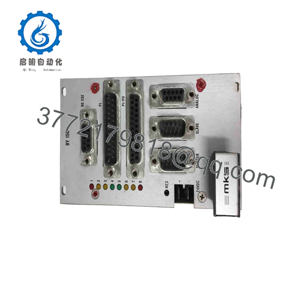
BY150
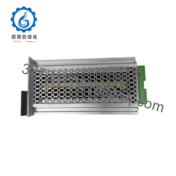
BY150
5. Troubleshooting Quick Reference
| Symptom | Possible Cause | Relevance to this Part | Quick Check Method | Recommendation |
|---|---|---|---|---|
| No synchronization / large lag | Encoder signals missing or noisy | ✅ High | Scope A/B/Z lines at terminals | Verify encoder wiring and 5 V supply first |
| Constant speed error | Ratio or scaling parameters wrong | ✅ High | Read parameters via LCD or OS 3.2 | Re-load correct ratio values |
| Unit does not power up | Supply voltage out of range | ✅ Medium | Measure 18–30 V DC at power connector | Check external 24 V supply |
| Analog output stuck | Enable or mode input incorrect | ✅ Medium | Check control-port logic levels | Confirm enable and direction signals |
| Intermittent registration fails | Marker pulse missing or polarity | ✅ High | Monitor Z-channel and marker input | Adjust marker edge or gain |
| Communication failure with PC | RS-232 cable or baud rate | ❌ Low | Verify pin-out (2-3 crossed) and settings | Use correct null-modem cable |
If the fault persists after these checks, photograph the front LEDs, connector wiring and parameter list, then contact technical support with the diagnostic data.
6. Frequently Asked Questions (FAQ)
Q: Can the BY150 synchronize any type of drive?
A: Yes, provided the drives accept a ±10 V analog speed reference. It works with AC inverters, DC drives and servo amplifiers. The physical limits of the drives still apply—the BY150 cannot force a drive beyond its own capability.
Q: Is the BY150 a direct replacement for older motrona Series 150 units?
A: Yes. Form factor, connector layout and most parameter addresses are compatible. Always transfer or re-enter the original ratio, scaling and marker settings after installation.
Q: Do I need the PC software or can I set everything from the front panel?
A: Both are possible. The front LCD and keypad cover all essential parameters. The OS 3.2 software is faster for complex setups and for saving/loading complete parameter files.
Q: What happens to the parameters if power is lost?
A: Parameters are stored in non-volatile EEPROM. A rising edge on the “Restore” input forces a write-back if you have changed values on the fly.
Q: Why is a surplus unit cheaper than a current-production equivalent?
A: The BY150 is an older high-performance analog-interface design. New-surplus stock is unused original material that still meets the full 300 kHz / 100 µs specification. Every unit is tested on a dual-encoder test bench before shipment.
Q: Any installation pitfalls I should watch for?
A: Keep encoder cables shielded and grounded at one end only. Confirm the analog speed reference polarity matches the drive direction. A clear photo of the original wiring before removal prevents most commissioning delays.



