WhatsApp: +86 16626708626
 Email:
 Phone: +86 16626708626
Description
Key Technical Specifications
The following specifications are based on Eaton’s MTL4500/4600 instruction manual and MTL4500 range datasheet.
| Parameter | Specification |
|---|---|
| Manufacturer | MTL / Eaton |
| Model | MTL4549Y |
| Product type | Dual-channel isolating driver |
| Application | 4–20 mA valve positioner and current-to-pressure converter interfaces |
| Number of channels | 2 |
| Input signal | Floating 4–20 mA |
| Output operating range | 4–20 mA |
| Supply voltage | 20–35 V DC |
| Maximum load resistance | 800 Ω |
| Minimum load resistance | 90 Ω |
| HART communication | Bidirectional digital signal transmission |
| HART signal bandwidth | 500 Hz to 10 kHz |
| Open-circuit detection | Yes; input current below 0.5 mA |
| Short-circuit detection | Not provided |
| Response time | Settles within 200 µA of final value within 100 ms |
| Transfer accuracy at 20°C | Better than 20 µA |
| Temperature drift | Less than 1.0 µA/°C |
| Hazardous-area application | Compatible field devices in suitably certified hazardous-area installations |
| Mounting and wiring | Follow the applicable MTL4500 installation manual |
Engineering note: The 90 Ω minimum load specification and the 800 Ω maximum load specification must be evaluated against the actual field device and loop configuration. Confirm the applicable hazardous-area certification, system control drawing, and installation requirements before commissioning.
Product Introduction
The MTL MTL4549Y is a dual-channel isolating driver in Eaton’s MTL4500 range. It interfaces floating 4–20 mA control signals from safe-area controllers with current-to-pressure converters or compatible valve positioners installed in hazardous areas. The module also passes bidirectional HART communication, allowing digital device information to be accessed from a control station or handheld communicator.
The key selection detail is its fault-detection behavior. The MTL4549Y detects open-circuit field wiring but does not detect short circuits. If a replacement is being considered for an MTL4549 or MTL4549C, verify the required fault-monitoring behavior, loop load, supply voltage, and HART compatibility before approving the substitution.
Installation & Configuration Guide
The MTL4549Y interfaces control-system outputs with field devices in hazardous areas. Installation must follow the applicable Eaton documentation, hazardous-area certification, and site wiring drawings. The procedure below is a general replacement workflow, not a substitute for the model-specific installation instructions.
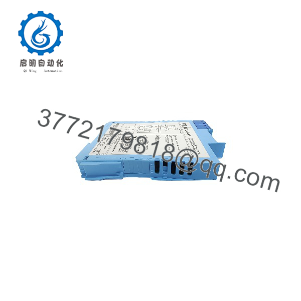
MTL4549Y
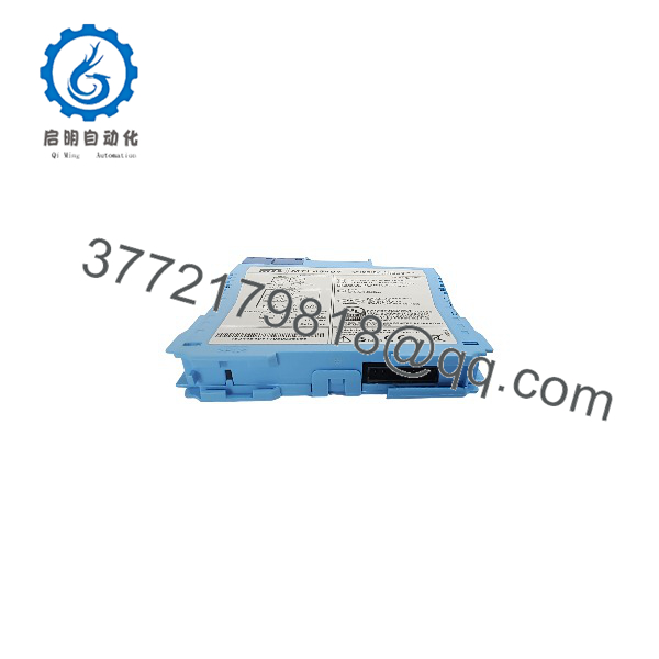
MTL4549Y
Stage 1: Pre-Installation Preparation
Estimated time: 10–15 minutes
- Confirm the exact model. Verify that the existing unit is MTL4549Y. Do not substitute MTL4549 or MTL4549C without checking their different fault-detection capabilities.
- Notify operations and place the affected control loops in an approved maintenance state. Confirm the safe state of the controlled valves or actuators.
- Apply lockout/tagout procedures to the relevant power and control circuits.
- Record both channels’ input wiring, field output wiring, power connections, and any HART communication arrangements.
- Document the controller’s output scaling, alarm thresholds, and field-device configuration.
- Check the field device’s current requirements, loop resistance, and applicable hazardous-area documentation.
Tools: Appropriate insulated hand tools, a multimeter suitable for the circuit, wire labels, the correct wiring diagram, and approved test equipment.
Stage 2: Removing the Existing Module
Estimated time: 5–10 minutes
- Verify that the relevant circuit has been isolated and is safe to work on.
- Label the wiring for Channel 1 and Channel 2 separately.
- Record the supply polarity and the safe-area input and hazardous-area output terminal assignments.
- Disconnect conductors using the manufacturer’s prescribed procedure. Avoid pulling on wires or applying force to terminals.
- Remove the module from its mounting arrangement.
- Inspect the mounting base and terminals for corrosion, loose connections, or signs of overheating.
⚠️ Hazardous-area warning: Do not disconnect or reconnect field wiring in a hazardous location unless the applicable area classification, permit, and installation procedures explicitly allow the work.
Stage 3: Installing the Replacement
Estimated time: 10–15 minutes
- Compare the replacement’s complete model number and hardware identification with the approved replacement specification.
- Confirm the power supply falls within the specified 20–35 V DC range.
- Connect the safe-area controller outputs and field-device circuits using the official terminal diagram.
- Verify Channel 1 and Channel 2 polarity independently.
- Confirm that each channel’s field load falls within the permitted resistance range.
- Check the HART communication path and ensure that the field device and control system support the intended communication arrangement.
- Inspect all connections before restoring power.
Installation checklist
Stage 4: Power-On and Functional Testing
Estimated time: 10–20 minutes
- Restore power according to the site’s approved commissioning procedure.
- Check the module’s status indication against the applicable Eaton manual.
- Apply a controlled 4–20 mA input to each channel using approved test equipment.
- Verify that the corresponding field output follows the command across the required operating range.
- Check the controlled device’s response and confirm that the PLC or DCS displays the expected feedback.
- If HART communication is required, verify digital communication using an appropriate communicator or control-system interface.
- Test the documented open-circuit fault response. Do not interpret the absence of short-circuit detection as a module failure; the MTL4549Y does not provide that function.
- Complete the site’s loop-check and acceptance records before returning the circuit to service.
⚠️ Do not force a valve to move solely to test the module. Coordinate actuator testing with operations and follow the approved process-safety procedure.
Frequently Asked Questions (FAQ)
Q1. What is the MTL4549Y used for?
The MTL4549Y is a dual-channel isolating driver for 4–20 mA control loops. It interfaces safe-area controllers with compatible current-to-pressure converters and valve positioners in hazardous-area applications. It also allows bidirectional HART communication.
Q2. What is the difference between MTL4549Y and MTL4549?
The key difference is short-circuit detection. The standard MTL4549 provides both open-circuit and short-circuit detection, while the MTL4549Y provides open-circuit detection only. If the existing control system relies on short-circuit detection, replacing the standard model with the Y variant could remove an important diagnostic capability.
Q3. Can I use the MTL4549Y with a HART valve positioner?
Yes, the module supports bidirectional HART communication for compatible field devices. Confirm the field device’s HART requirements, loop resistance, wiring arrangement, and control-system integration before installation.
Q4. What power supply does the MTL4549Y require?
The documented supply range is 20–35 V DC. Verify the actual supply voltage at the module terminals and check the installation manual for the applicable supply and wiring requirements.
Q5. Can the MTL4549Y replace an MTL4549C?
Do not approve the substitution based on model similarity alone. The MTL4549C and MTL4549Y both provide open-circuit detection without short-circuit detection, but you should still confirm the exact hardware revision, electrical requirements, certification, mounting arrangement, and system documentation before replacement.
Q6. Is the MTL4549Y obsolete, and is new stock available?
The manufacturer’s documentation confirms the product family and technical function, but this alone does not establish current manufacturing status or stock availability. Request a current quotation and written confirmation of condition, quantity, lead time, and warranty. For surplus inventory, ask for photographs of the actual unit and its nameplate.
Q7. What should I verify before ordering?
Confirm the full model number, required quantity, condition, and delivery requirements. For technical approval, prioritize:
- Two-channel 4–20 mA compatibility
- 20–35 V DC supply requirements
- Field-device load resistance
- HART communication requirements
- Open-circuit versus short-circuit diagnostic requirements
- Hazardous-area certification and system compatibility
- Warranty and return terms