
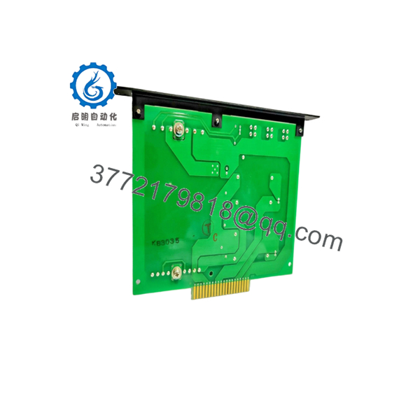
 WhatsApp: +86 16626708626
 Email:
  Phone: +86 16626708626
Description
Key Technical Specifications
| Parameter | Value |
|---|---|
| Manufacturer | NABCO |
| Model | MCA-601-01 |
| Product Type | Printed Circuit Board / Power Supply PCB |
| Part Number | 881 73748379 |
| Additional Identification | K1650627 |
| Alternate Identification | K960219 / K990215 |
| Application | Marine automation / main engine control |
| System | NABCO M-800 / M-800-II related control equipment |
| Board Function | Power supply / control-system circuitry |
| Weight | Approximately 370 g |
| Supply Voltage | Not publicly verified |
| Output Voltage | Not publicly verified |
| Communication Interface | Not publicly verified |
| Operating Temperature | Not publicly verified |
Specialist marine-equipment sources identify NABCO MCA-601-01 as a PCB with part number 881 73748379. Shipcare+ Japan additionally lists K960219 and K990215 as associated identification numbers.
A marine spare-parts database lists MCA-601-01 under the NABCO M-800-II main-engine remote-control system and identifies related entries as PCB MCA-601-01.
A current specialist listing gives K1650627 as an associated identification and a weight of approximately 370 g.
⚠️ Electrical specification limitation: Public sources do not establish the exact input/output voltage, current rating, fuse arrangement, connector pinout, or environmental ratings for this exact board. These values must be verified from the applicable NABCO documentation or the actual PCB before installation.
Product Introduction
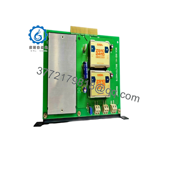
The NABCO MCA-601-01 is a NABCO printed circuit board used in marine engine-control equipment. Current specialist records associate it with 881 73748379, while marine-equipment documentation places the MCA-601-01 within NABCO M-800-series control applications.
The board is particularly relevant for maintaining legacy NABCO main-engine control installations. One specialist source describes the as a power supply PCB, while another identifies it more generally as a PCB module. Because these descriptions differ in detail, verify the installed system drawing and board markings before treating the card as a specific power-supply replacement.
MCA-601-01
Installation & Configuration Guide
Stage 1: Pre-Installation Preparation — Approximately 10 Minutes
⚠️ Safety First: Notify vessel operations and obtain approval for the maintenance window. Put the main-engine control system into its approved safe state, isolate the relevant electrical supplies, and follow the vessel’s lockout/tagout procedure.
Tools Required
- ESD wrist strap
- Grounded ESD work surface
- Appropriate screwdriver set
- Digital multimeter
- Wire and connector labels
- Smartphone or camera
- NABCO system drawings and maintenance documentation
Data Backup
- Record the complete model marking.
- Record 881 73748379 and all additional identification numbers.
- Photograph the PCB before removal.
- Photograph every connector and terminal position.
- Document fuse, jumper, switch, and link positions if fitted.
- Photograph the surrounding power-panel wiring.
- Record active alarms and system status before shutdown.
- Retain the original PCB until the replacement has passed commissioning.
⚠️ Do not identify this board from “MCA-601” alone. The complete suffix -01 and the associated part number 881 73748379 should match the procurement documentation.
Stage 2: Removing the Old Module — Approximately 5 Minutes
- Confirm that the main-engine control system is in the approved maintenance state.
- Isolate the applicable power supplies.
- Verify absence of hazardous voltage with an appropriate meter.
- Establish ESD protection.
- Remove the required power-panel or control-panel cover.
- Photograph the installed and connector arrangement.
- Label connectors if there is any possibility of incorrect reconnection.
- Disconnect connectors carefully without pulling individual wires.
- Release the PCB retaining hardware.
- Remove the card without flexing or damaging the PCB.
- Inspect mating connectors, terminals, and mounting points for corrosion or heat damage.
⚠️ Keep the removed card for comparison. If the replacement does not power the system correctly, the original board can help identify connector, fuse, jumper, and revision differences.
Stage 3: Installing the New Module — Approximately 5–10 Minutes
- Verify the replacement marking: .
- Verify part number 881 73748379.
- Compare all additional markings with the original board.
- Compare connector locations and mounting points.
- Check the board revision before installation.
- Confirm board orientation.
- Inspect connectors for bent or contaminated contacts.
- Install the PCB without forcing any connector.
- Secure the board using the original mounting hardware.
- Reconnect each connector according to the photographs and approved wiring diagram.
- Confirm that every connector is fully seated.
Configuration Clone — Critical
If the original contains jumpers, links, switches, or fuse configurations, document and reproduce the approved settings exactly.
Do not assume that a replacement PCB is configured identically to the removed board.
Pre-Power Checklist
- model verified
- 881 73748379 part number verified
- Additional identification checked
- Connector arrangement verified
- Board orientation correct
- Fuse and jumper configuration checked
- Wiring checked against photographs
- Mounting hardware secured
- No visible PCB damage
- No loose conductive material inside the panel
Stage 4: Power-On & Testing — Approximately 10–15 Minutes
- Perform a final visual inspection.
- Confirm that all tools and loose hardware have been removed.
- Verify the applicable supply circuits against the NABCO drawing.
- Check for accidental shorts before energizing.
- Restore power according to the approved vessel procedure.
- Observe PCB and control-panel indicators.
- Check for abnormal alarms or power-supply faults.
- Verify the control system’s power-source status.
- Confirm communication with associated NABCO control equipment where applicable.
- Perform the manufacturer’s prescribed functional test.
- Confirm that the main-engine control system returns to its expected operating state.
- Record the replacement part number, board identification, and test results.
⚠️ Do not assume a particular LED indication means a specific fault without the correct NABCO manual. Public sources do not provide a reliable diagnostic table for .
Frequently Asked Questions (FAQ)
What is the NABCO ?
The is a printed circuit board used in NABCO marine engine-control equipment. Specialist sources identify 881 73748379 as its principal part number.
What is the part number for NABCO ?
The principal documented part number is 881 73748379. Additional identification numbers appear in specialist inventory records, including K1650627, K960219, and K990215.
Is the a power supply PCB?
Some current listings specifically describe the as a power supply module PCB, while other specialist marine suppliers simply identify it as a PCB card or PCB module.
For procurement and engineering documentation, it is safer to identify it by the exact model and part number rather than assigning an unverified electrical function.
Which NABCO system uses ?
A marine spare-parts database lists under the NABCO M-800-II main-engine remote-control system, including multiple PCB entries.
A separate marine engineering source also records a NABCO power-panel supply project, supporting its use in marine control-panel applications.
Can the NABCO be hot-swapped?
Do not assume that it can. This board is associated with marine engine-control and power-panel equipment, and the sources reviewed do not establish an approved hot-swap procedure. Isolate the relevant power before removal unless the applicable NABCO documentation explicitly permits energized replacement.
Is NABCO obsolete?
The sources reviewed do not provide an official NABCO end-of-life announcement. However, the board is predominantly found through specialist marine-spares channels, including new and used inventory.
For a critical-spares program, treat it as a legacy component and verify long-term availability rather than assuming continued OEM production.
Is the available new?
Yes, specialist inventory currently includes units listed as New or New without box. Other suppliers list used units, so condition varies by source.
When purchasing, specify New Original / New Surplus or Refurbished / Tested explicitly. Request photographs of the actual PCB, complete identification markings, inspection or test records, and warranty terms before issuing a purchase order.



