
 WhatsApp: +86 16626708626
 Email:
  Phone: +86 16626708626
Description
Technical Specifications
| Parameter | Specification |
|---|---|
| Manufacturer | NABCO |
| Model | MU-190-01 |
| Product Type | Control PCB / Electronic Module |
| Series | MU |
| Application | Marine control system |
| Board Function | System-specific control circuitry |
| Supply Voltage | Not publicly verified |
| I/O Configuration | Not publicly verified |
| Communication Interface | Not publicly verified |
| Power Consumption | Not publicly verified |
| Operating Temperature | Not publicly verified |
| Dimensions | Not publicly verified |
| Weight | Not publicly verified |
| Mounting Method | Not publicly verified |
Technical accuracy note: The available information does not establish the exact function, voltage rating, connector pinout, I/O architecture, communications interface, dimensions, or environmental specifications of the NABCO MU-190-01. These values should be confirmed from the applicable NABCO documentation or the identification markings on the actual board.
Product Introduction
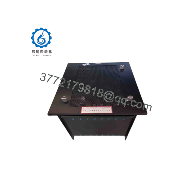
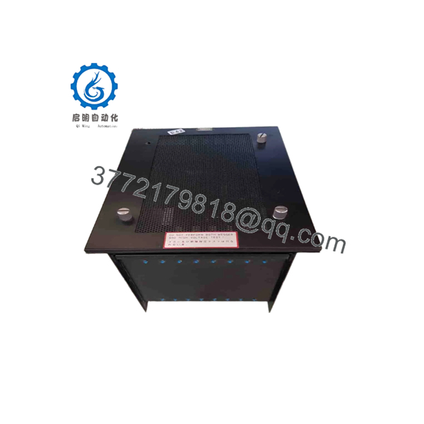
The NABCO MU-190-01 is a NABCO electronic control module associated with marine automation equipment. The complete model designation, including the -01 suffix, should be used when identifying a replacement.
Because detailed public technical information for this specific model is limited, procurement should be based on the complete part marking and the installed system configuration rather than assumptions about the MU-series product family.
For legacy marine control equipment, an exact physical match is particularly important. Verify connector placement, board revision, mounting arrangement, and any additional part numbers before installation.
MU-190-01
Installation & Configuration Guide
Stage 1: Pre-Installation Preparation
⚠️ Safety First: Place the affected marine control equipment into its approved maintenance state. Isolate the applicable electrical supply and follow the vessel’s lockout/tagout procedures.
Required Tools
- ESD wrist strap
- Grounded ESD work surface
- Appropriate screwdriver set
- Digital multimeter
- Connector labels
- Camera or smartphone
- Applicable NABCO system drawings
Before Removing the Existing Unit
- Record the complete MU-190-01 model marking.
- Photograph all identification labels.
- Photograph the PCB and surrounding equipment.
- Photograph every connector before removal.
- Record jumper, switch, or link positions if fitted.
- Record relevant system alarms.
- Confirm the replacement part against the original before proceeding.
⚠️ Do not identify the replacement solely as “MU-190.” The complete MU-190-01 designation should match the installed equipment documentation.
Stage 2: Removing the Existing Module
- Confirm the system is in a safe maintenance state.
- Isolate the applicable power.
- Verify the absence of hazardous voltage.
- Establish ESD protection.
- Remove the appropriate enclosure or rack cover.
- Photograph the installed module.
- Label connectors where necessary.
- Disconnect connectors carefully.
- Remove retaining hardware.
- Remove the module without bending or flexing the PCB.
- Inspect connectors and mounting points for corrosion or damage.
Keep the original unit until the replacement has completed functional testing.
Stage 3: Installing MU-190-01
- Verify the marking NABCO MU-190-01.
- Compare all additional identification numbers with the original.
- Compare connector locations.
- Confirm mounting-hole positions.
- Verify board orientation.
- Inspect connectors for bent or contaminated contacts.
- Install the module without forcing it into position.
- Secure the mounting hardware.
- Reconnect each connector according to the original photographs and wiring documentation.
- Confirm that all connectors are fully seated.
- Inspect the installation for loose hardware or conductive debris.
Configuration
If the original MU-190-01 contains configurable jumpers, switches, links, or other settings, document them before removal and reproduce the approved configuration on the replacement.
Do not assume that the replacement has the correct field configuration by default.
Pre-Power Checklist
- MU-190-01 model verified
- Complete identification checked
- Connector arrangement verified
- Board orientation correct
- Wiring checked
- Jumper/switch configuration documented
- Mounting hardware secured
- PCB visually inspected
- No conductive debris present
Stage 4: Power-On and Functional Testing
- Perform a final visual inspection.
- Confirm all tools and loose hardware have been removed.
- Verify the applicable supply circuit against the system drawing.
- Restore power using the approved startup procedure.
- Observe system and module status indicators.
- Check for new alarms.
- Verify associated control-system communication where applicable.
- Perform the manufacturer’s prescribed functional test.
- Confirm the affected control functions operate correctly.
- Record the replacement model and test results.
⚠️ Do not assign LED meanings, voltage thresholds, or signal limits without the applicable NABCO documentation.
Frequently Asked Questions
What is NABCO MU-190-01?
NABCO MU-190-01 is a NABCO electronic control module/PCB associated with marine automation equipment. Publicly available information does not provide enough detail to establish its exact internal circuit function.
What does MU-190-01 do?
The exact functional role is not sufficiently verified. It should therefore be described as a system-specific NABCO control module rather than labeling it as a CPU, I/O card, power supply, or communication module without supporting documentation.
Is MU-190-01 a PLC CPU?
There is insufficient evidence to classify the MU-190-01 as a conventional PLC CPU. The model designation alone does not establish its internal architecture.
Can another NABCO MU-series module replace MU-190-01?
Do not assume compatibility. Verify the complete model number, revision, connector layout, electrical requirements, mounting configuration, and system documentation before substitution.
Can MU-190-01 be hot-swapped?
Do not assume hot-swapping is permitted. Unless the applicable NABCO documentation explicitly specifies energized replacement, isolate the relevant power before removing the module.
Is NABCO MU-190-01 obsolete?
There is insufficient information to make an official end-of-life determination. For inventory planning, treat the part as a legacy marine-control spare until its current OEM availability and lifecycle status are confirmed.
What should I verify before purchasing MU-190-01?
Request photographs of the actual unit showing:
- MU-190-01 marking
- Additional part numbers
- Revision information
- Connector arrangement
- PCB condition
- Manufacturer markings
For a critical marine application, also specify the required condition—New Original / New Surplus or Refurbished / Tested—and request inspection or functional-test records before purchase.



