
 WhatsApp: +86 16626708626
 Email:
  Phone: +86 16626708626
Description
Key Technical Specifications
| Parameter | Specification |
| Model Number | MU-417-01 |
| Manufacturer | NABCO (Nabtesco Corporation) |
| Primary Application | Marine main engine remote control, bridge/ECR monitoring, and alarm indication |
| Display / Interface | High-visibility status LEDs, multi-segment alarm indicators, and function switches |
| Supply Voltage | 24 V DC nominal (±10%) |
| Input Signals | Opto-isolated digital alarm inputs, system health signals, and control mode handshakes |
| Output Signals | Common alarm relay contact outputs, buzzer trigger signals, auxiliary serial telemetry |
| Operating Temperature | -10°C to +60°C (14°F to 140°F) |
| Enclosure Type | Flush panel-mount console unit with rear heavy-duty terminal interface |
| Weight | 1.85 kg (4.08 lbs) |
Product Introduction & Supply Chain Strategy
The NABCO MU-417-01 is a dedicated Monitor Unit (MU) designed for integration into NABCO main engine remote control consoles. Positioned at the Bridge or Engine Control Room (ECR) desk, it provides continuous status indication, operating mode monitoring, and alarm processing for main propulsion pneumatic and electronic systems.
Carrying a genuine New Surplus MU-417-01 in vessel spare inventory is a critical risk mitigation measure for marine engineers. Monitor unit failures blind operators to propulsion system health and fault codes, forcing emergency manual engine operation and risking class inspection deficiencies during port state controls. Sourcing unused original inventory guarantees fresh LED display elements, undegraded internal power stages, and complete reliability, avoiding the high failure rates of second-hand units while bypassing extended OEM production lead times.
Installation & Configuration Guide
Stage 1: Pre-Installation (Prep & Safety)
- Power Isolation: Open the 24V DC circuit breakers supplying power to the ECR or Bridge monitoring console. Confirm zero voltage on power terminal leads using a calibrated digital multimeter.
- ESD Safety: Wear a grounded ESD wrist strap before handling internal wiring harness plugs or rear terminal connections.
- Record Cabling: Document and photograph all rear multi-pin plug alignments and cable identification tags on the existing unit.
Stage 2: Removal
- Unfasten rear terminal block screws or unclip multi-pin harness connectors from the unit chassis.
- Loosen the front panel mounting fasteners or side panel retaining clamps securing the unit in the console cutout.
- Gently pull the MU-417-01 forward out of the desk cutout, taking care not to snag surrounding wiring harnesses.
Stage 3: Installation (Clone & Seat)
- Align the DIP switch arrays and rear jumper blocks on the replacement MU-417-01 to match the original unit’s settings.
- Slide the replacement module into the console cutout and tighten mounting clamps to 1.2 N·m.
- Reattach all multi-pin harness connectors and secure locking screws firmly.
Stage 4: Power-On & Testing
- Re-apply 24V DC auxiliary power. Verify the power LED lights up and the unit completes its lamp test/power-on self-check.
- Trigger a simulated alarm input from the main control panel to verify proper LED indication and audible buzzer response.
- Validate mode status indicators (Bridge Control, ECR Control, Local Control) during system selection tests.
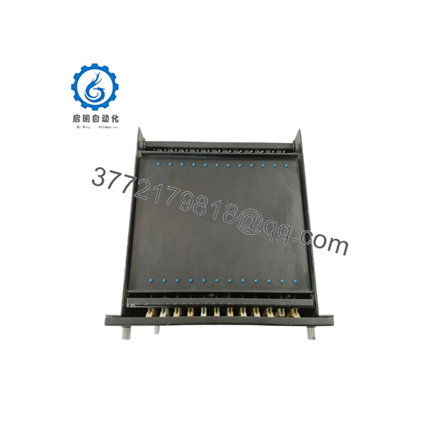
MU-417-01
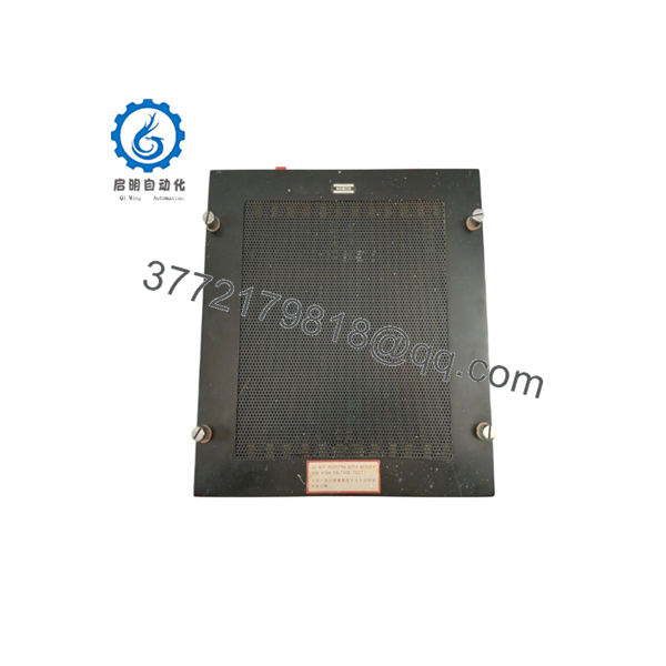
MU-417-01
Firmware/Software Versions & Upgrade Notes
- Hardware-Based Microcode: The MU-417-01 utilizes onboard factory-programmed EPROMs. External laptop flashing or field software setup is not required during hardware installation.
- Revision Verification: Confirm that the primary model designation
MU-417-01matches your target panel cutout and wiring schematic. Variant sub-revisions may feature different LED color arrangements or terminal block pin allocations. - Jumper Configuration Warning: Do not alter onboard configuration jumpers without referring to the ship’s specific NABCO console wiring diagram, as incorrect settings can ground common alarm output lines.
Frequently Asked Questions (FAQ)
Is this NABCO MU-417-01 unit brand new or refurbished?
This product is a Brand New Surplus unit. It is not used, not pulled from a decommissioned vessel, and not refurbished. All assemblies undergo quality verification to ensure OEM-level reliability.
Why choose New Surplus over a refurbished monitor unit for marine consoles?
Refurbished monitor panels frequently suffer from dimmed status LEDs, cracked solder joints caused by continuous vessel vibration, and age-degraded logic capacitors. A monitor failure during maneuvering deprives the crew of critical system alarm warnings. New Surplus provides original component integrity, full 10–15 year lifespan, and complete reliability at a fraction of factory list price.
What is the primary role of the MU-417-01 in the propulsion control system?
The MU-417-01 acts as the human-machine display interface for the engine remote control system. It consolidates control location status, system fault conditions, and operational readiness signals into visual and audible indications for the ship’s officers.
Does replacing the MU-417-01 require field software commissioning?
No laptop programming is needed. You only need to align the physical DIP switches/jumpers on the new board to match the original unit before restoring cabinet power.
What warranty protection comes with this New Surplus monitor unit?
Every NABCO MU-417-01 unit supplied from our New Surplus stock is backed by a 1-year functional replacement warranty.



