WhatsApp: +86 16626708626
 Email:
 Phone: +86 16626708626
Description
Core Product Summary
The NEXCOM PEAK715VL-HT(LF) is a full-size PICMG 1.0 single board computer (SBC) in NEXCOM’s PEAK 715-HT series, a Pentium 4-based CPU card family designed for passive-backplane industrial computers. The board carries an Intel 845GV chipset with an ICH4 I/O controller hub and a Socket 478 for Intel Pentium 4/Celeron processors up to 3.06 GHz (400/533 MHz FSB, Hyper-Threading) or Intel Pentium 4-M processors up to 2.4 GHz with a 400 MHz FSB.
It supports up to 2 GB of unbuffered non-ECC DDR SDRAM on two 184-pin DIMMs and provides integrated VGA with 64 MB shared memory, one Intel 82551QM 10/100 Fast Ethernet controller, four USB 2.0 ports, two Ultra DMA IDE channels, and a programmable watchdog timer (1–128 seconds). Power is drawn from the backplane through the PCI/ISA edge connector, with AT and ATX power modes supported. The “(LF)” ordering suffix identifies the RoHS-compliant version of the board.
Key Technical Specifications
| Parameter | Value |
|---|---|
| Product type | Full-size PICMG 1.0 single board computer (CPU card) |
| Series | NEXCOM PEAK 715-HT |
| Order part number | 10P0715HT02X0 |
| RoHS status | RoHS compliant (LF version) |
| CPU socket | Socket 478 |
| Processor support | Intel Pentium 4 / Celeron up to 3.06 GHz with 400/533 MHz FSB, Hyper-Threading technology; Intel Pentium 4-M up to 2.4 GHz with 400 MHz FSB |
| Chipset | Intel 845GV + Intel 82801DB (ICH4) |
| Memory | 2 × 184-pin DIMM, up to 2 GB unbuffered non-ECC DDR 200/266/333 SDRAM |
| Graphics | Intel 82845GV integrated VGA controller, 64 MB shared system memory |
| Ethernet | 1 × Intel 82551QM 10/100 Fast Ethernet controller, full duplex per IEEE 802.3/802.3u/802.3x/802.3y/802.3ab, RJ45 with LED |
| USB | 4 × USB 2.0 (480 Mbps) |
| Storage interface | 2 × 40-pin IDE connectors, Ultra DMA 33/66/100 |
| Serial ports | 2 (2×5-pin header) |
| Parallel port | 1 × 26-pin connector, EPP/ECP support |
| Other I/O | FDD (34-pin), 15-pin CRT video, PS/2 keyboard/mouse (6-pin Mini-DIN), 5-pin external keyboard, GPIO (4 in / 4 out), I²C header, optional CompactFlash socket |
| Super I/O | ITE 8712F-A |
| BIOS | Award system BIOS, 4 Mbit flash ROM, Plug & Play, APM and ACPI support |
| Watchdog timer | Programmable, 1–128 seconds |
| System monitoring | 8 voltage inputs (+1.5 V, +3.3 V, +5 V, −5 V, +12 V, −12 V, Vcore, 5 V standby), 2 fan speeds, 2 temperature inputs |
| RTC | On-chip real-time clock with external Li-Ion battery backup |
| Power source | Backplane through PCI/ISA edge connector; AT or ATX power mode |
| Maximum power consumption on board | 5 V: 4 A; 12 V: 6.5 A; 3.3 V: 0.6 A; 5 Vsb: 0.5 A |
| Operating temperature | 0 °C to 60 °C |
| Storage temperature | −20 °C to 80 °C |
| Relative humidity | 10% to 90%, non-condensing |
| Dimensions | 338.58 mm (L) × 122 mm (W) |
| Certifications | CE approval, FCC Class A |
Detailed Product Overview
The PEAK715VL-HT(LF) belongs to the segment of industrial computing where the CPU does not live on a standalone motherboard but on a plug-in card that seats into a passive backplane inside an industrial chassis. This architecture is what makes the board interesting for system integrators: the SBC concentrates the processor, memory, and core I/O, while expansion slots, power distribution, and mounting are provided by the backplane and chassis. The PEAK 715-HT series is documented as compatible with multi-segmented backplanes and power supplies, which matters when the target chassis hosts several segments or an unusually high number of expansion cards.
The platform choice defines the integration envelope. The Intel 845GV chipset pairs with the ICH4 south bridge, giving the board two Ultra DMA IDE channels, USB 2.0 at 480 Mbps across four ports, and an integrated graphics controller with 64 MB of shared memory — enough for a standard CRT display on the 15-pin VGA connector without a separate graphics card. Memory support covers up to 2 GB of unbuffered non-ECC DDR SDRAM in two 184-pin DIMM sockets, with DDR333 noted as the supported double-data-rate grade in the series manual.
The “(LF)” suffix in the order number identifies the RoHS-compliant configuration, and the full order part number 10P0715HT02X0 is what distinguishes this single-LAN model from its series siblings that carry dual LAN controllers. For network design, this board carries one Intel 82551QM 10/100 Fast Ethernet controller behind an RJ45 connector with status LEDs.
Two engineering details deserve attention at selection time. First, power: the board is not powered by a dedicated ATX connector like a desktop board. It draws power from the backplane through the PCI/ISA edge connector, and the 3.3 V rail is generated on board from the 5 V supply rather than taken from the backplane. The 5 V standby rail is routed from the backplane through a 3-pin cable connector, and an additional 4-pin +12 V power input connector is provided. The board supports both AT and ATX power modes, configured by jumper (J28/J17). Budgeting should use the documented maximums: 4 A at 5 V, 6.5 A at 12 V, 0.6 A at 3.3 V, and 0.5 A at 5 Vsb. Second, supervision: a programmable watchdog timer with a 1–128 second range lets control software recover an unattended system, and the hardware monitoring functions (voltage, fan speed, and temperature inputs derived from the ITE 8712F-A Super I/O) allow chassis health to be polled by application software.
Configuration is jumper-based: CMOS clear (JP2), CPU type (JP3), and the power mode jumpers cover the settings an integrator is most likely to touch during commissioning or CPU changes. Memory population uses two DIMM banks mapped to the DIMM1 and DIMM2 sockets.
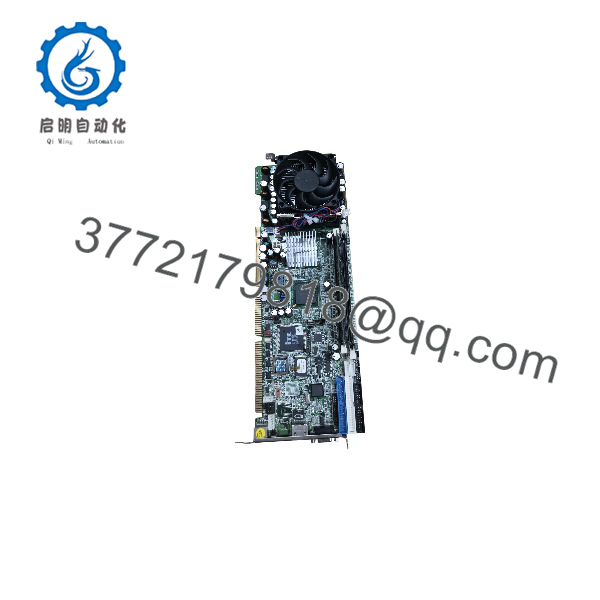
PEAK715VL-HT(LF)
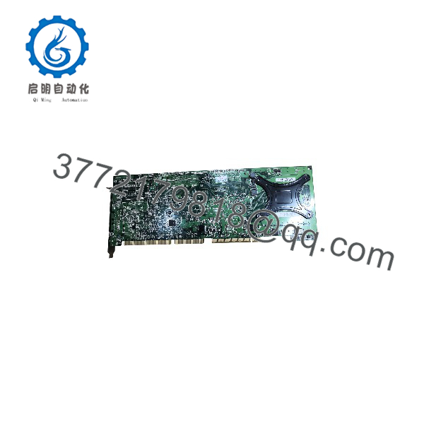
PEAK715VL-HT(LF)
Dimensions, Mounting & Connection Notes
- Board dimensions: 338.58 mm (L) × 122 mm (W) — full-size SBC card format.
- Mounting: Installed as an edge-card into a PICMG 1.0 backplane slot; the board is a card-mount PC board for system assembly within an industrial chassis.
- Bracket I/O: 1 × VGA DB-15 connector, RJ45 Ethernet LAN port, 1 × Mini-DIN for keyboard/mouse.
- On-board connectors: 15-pin CRT video, 2 × 40-pin IDE, 34-pin FDD, 26-pin parallel (EPP/ECP), 6-pin Mini-DIN PS/2, 5-pin external keyboard connector, 4 × USB 2.0, serial port 2×5-pin headers.
- Control/status headers: reset switch (2-pin), IDE active LED (2-pin), ATX power switch (2-pin), buzzer, GPIO (4 in / 4 out), I²C (2-pin).
- Power connectors: 3-pin power header for the backplane ATX power-on cable; 4-pin additional +12 V power input header.
- Environmental installation limits: 0 °C to 60 °C operating, −20 °C to 80 °C storage, 10%–90% relative humidity non-condensing.
- Battery: external Li-Ion battery for RTC backup.
System Compatibility & Integration Requirements
| Item / Dependency | Verified Compatibility or Requirement | Practical Note |
|---|---|---|
| Form factor | Full-size PICMG 1.0 single board computer | Requires a PICMG 1.0 passive backplane and compatible industrial chassis |
| Backplane compatibility | Documented as compatible with multi-segmented backplanes and power supplies | Verify backplane slot type and segment count before installation |
| Power mode | Supports AT or ATX power supplies; mode set via jumpers J28/J17 | Confirm the chassis power supply type matches the jumper configuration |
| Standby power | 5 Vsb supplied from backplane via 3-pin power cable connector | Cable to backplane required for ATX power-on function |
| 3.3 V rail | Generated on board from +5 V; not taken from backplane or supply | Backplane does not need to provide 3.3 V to this slot |
| Additional power | On-board 4-pin +12 V additional power source input header | Use per chassis/installation documentation |
| ISA expansion | ITE 8888F PCI-to-ISA bridge; high-drive ISA signals support up to 20 ISA cards on backplane ISA slots | Relevant when legacy ISA I/O cards remain in the system |
| Expansion I/O headers | 2 serial ports (2×5-pin headers), parallel (26-pin), FDD (34-pin), GPIO (4 in / 4 out), I²C 2-pin header | Serial/parallel connections require appropriate header cables or brackets |
| BIOS configuration | Award BIOS, 4 Mbit flash ROM, APM/ACPI, Plug & Play | CMOS clear jumper JP2; CPU type jumper JP3 |
| Driver support | VGA, INF, and Intel Application Accelerator driver installation documented in the series manual | Driver CD supplied with the board package |
FAQ
What is the NEXCOM PEAK715VL-HT(LF)?
It is a RoHS-compliant, full-size PICMG 1.0 single board computer from NEXCOM’s PEAK 715-HT series, carrying a Socket 478 CPU, Intel 845GV/ICH4 chipsets, and one 10/100 Ethernet controller, with the order part number 10P0715HT02X0.
Which processor can it run?
It supports Intel Pentium 4 and Celeron processors up to 3.06 GHz with a 400/533 MHz front-side bus and Hyper-Threading technology, or Intel Pentium 4-M processors up to 2.4 GHz with a 400 MHz FSB.
How much memory does it support?
Up to 2 GB of unbuffered non-ECC DDR SDRAM across two 184-pin DIMM sockets, supporting DDR 200/266/333 modules.
What backplane and chassis does it require?
It requires a full-size PICMG 1.0 passive backplane in a compatible industrial chassis; the series is documented as compatible with multi-segmented backplanes and power supplies.
How is the board powered?
Power comes from the backplane through the PCI/ISA edge connector, supporting AT or ATX power supplies (mode selected by jumpers). The board generates its own 3.3 V rail from 5 V, receives 5 Vsb through a 3-pin cable from the backplane, and provides a 4-pin +12 V additional power input header. Maximum consumption is 4 A at 5 V, 6.5 A at 12 V, 0.6 A at 3.3 V, and 0.5 A at 5 Vsb.
What I/O does it provide?
Four USB 2.0 ports, two IDE channels (Ultra DMA 33/66/100), two serial ports via pin headers, one parallel port with EPP/ECP, a floppy interface, integrated VGA on a 15-pin CRT connector, PS/2 keyboard/mouse, GPIO (4 in / 4 out), an I²C header, and an optional CompactFlash socket.
Does it support unattended operation?
Yes — it includes a programmable watchdog timer with a 1–128 second range, plus hardware monitoring of eight voltages, two fan speeds, and two temperatures through the ITE 8712F-A Super I/O chip.
Can it drive legacy ISA cards?
Yes. An ITE 8888F PCI-to-ISA bridge provides high-drive ISA signals and supports up to 20 ISA cards on backplane ISA slots.
What are its operating limits?
Operating temperature is 0 °C to 60 °C, storage temperature −20 °C to 80 °C, and relative humidity 10% to 90% non-condensing. The board carries CE approval and FCC Class A certification.