WhatsApp: +86 16626708626
 Email:
 Phone: +86 16626708626
Description
Key Technical Specifications
NI lists specifications as typical at 25 °C unless otherwise noted. Output current depends on temperature and the number of active lines; do not apply the single-line rating to every output simultaneously.
| Parameter | Value |
|---|---|
| Digital Input Channels | 32 sink/source inputs; ports P0–P3 |
| Digital Output Channels | 32 sourcing outputs; ports P4–P7 |
| Isolation Arrangement | Eight banks of eight lines; shared ground and/or power within each bank |
| Common-Mode Isolation | 30 V DC, bank-to-bank and bank-to-bus |
| Input Logic Thresholds | Low: magnitude ≤4 V DC; high: magnitude 11–30 V DC relative to the applicable input COM |
| Input Current | Maximum 4.5 mA/line at 11 V; maximum 12.5 mA/line at 30 V |
| Output Supply and Switching | External 5–30 V DC supply; maximum switching voltage: 30 V DC |
| Output Current at 25 °C | 75 mA per line with all eight lines in a port active; 350 mA with only one line in a port active |
| Typical Propagation Delay | Input: 75 µs; output: 80 µs with a 100 Ω load |
| Startup and Monitoring | Default output state: 0/open; programmable power-up states; 400 ms power-up-state response; watchdog timer |
| Host Interface and Power | Conventional PCI; typical bus draw: 250 mA at +5 V and 300 mA at +3.3 V |
| Connector and Environment | 100-pin keyed female SCSI; operating temperature: 0–55 °C; 10–90% RH, noncondensing; indoor use |
Specifications and port assignments come from NI’s NI 651x specifications and user manual.
PCI-6514 Output Current Derating
| Ambient Temperature | Per-Line Limit With All Eight Lines Active in a Port | Limit With Only One Line Active in a Port |
|---|---|---|
| Up to 25 °C | 75 mA | 350 mA |
| Up to 35 °C | 65 mA | 350 mA |
| Up to 45 °C | 55 mA | 350 mA |
| Up to 55 °C | 50 mA | 300 mA |
These are PCI-specific limits. NI notes that airflow, I/O voltage, usage, and duty cycle can further affect operating temperature and available current. Each output port includes a self-resetting overcurrent fuse.
❗ Warning: “350 mA output” is not a 32-channel simultaneous rating. At 25 °C, NI limits each line to 75 mA when all eight lines in its port operate together.
Product Introduction
The NI PCI-6514 is an industrial PCI digital I/O card with 32 sink/source inputs and 32 sourcing outputs. Eight optically isolated banks interface host software with field signals and externally powered DC loads.
Programmable power-up states, input filtering, change detection, and a watchdog timer support defined startup and fault-response behavior. Choose it when sourcing outputs match the existing wiring; it is not interchangeable with the sinking-output PCI-6515 without an electrical compatibility review.
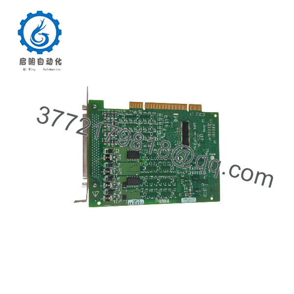
PCI-6514
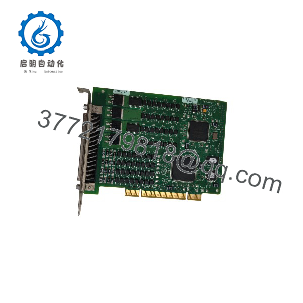
PCI-6514
Troubleshooting Quick Reference
| Symptom | Possible Cause | Relevance to this Part | Quick Check Method | Recommendation |
|---|---|---|---|---|
| Card missing from NI MAX | Unsupported driver/OS combination, poor seating, or PCI slot problem | Possible hardware issue; not established | Check OS enumeration; refresh MAX; verify driver support; shut down and unplug before trying another compatible slot | Confirm host and driver operation before replacing |
| All eight outputs in one port fail | Missing field supply, incorrect COM wiring, or tripped port fuse | External wiring or overload first | Measure the affected port’s Pn.VCC relative to Pn.COM/GND; verify 5–30 V DC under load | Restore supply or remove overload before retesting |
| Output command changes but load stays off | Sourcing/sinking mismatch, open load circuit, or damaged output | Wiring check required | Measure Pn.x relative to that output port’s COM/GND with a suitable test load; confirm load connects between output and COM/GND | Correct sourcing-output wiring before condemning the card |
| Outputs stop after warming up | Excess port loading or inadequate thermal margin | Current derating directly relevant | Measure individual load currents; record ambient temperature and active outputs per port | Reduce loading or use an appropriately rated external driver |
| Input remains low with a field signal present | Missing bank COM, low signal voltage, wrong channel, or cable fault | Wiring/threshold issue first | Measure P0–P3 input voltage relative to the matching Pn.COM; verify magnitude reaches 11–30 V | Correct reference and signal level; avoid exceeding 30 V |
| Short input pulses disappear | Digital filter rejects pulses or photocoupler timing limits recognition | Expected behavior possible | Read the configured filter interval; repeat with longer pulses and filtering disabled where safe | Match filtering to the required pulse duration |
| Outputs stop responding after an application fault | Watchdog expired | Documented behavior; not proof of damage | Inspect watchdog expiration status and configured timeout | Follow the documented disarm/recovery sequence before writing outputs |
| Output state differs during startup | Stored power-up configuration or startup response timing | Configuration issue possible | Read power-up settings in MAX; capture startup behavior with loads safely isolated | Validate startup and watchdog states before reconnecting actuators |
Checks follow NI’s wiring, current protection, input filtering, startup, and watchdog documentation. They do not establish a field failure rate.
If the fault remains, contact technical support with board-label photos, cable and terminal-block identifiers, bank wiring photos, measured supply/load values, NI-DAQmx version, exact errors, and diagnostic logs.
Frequently Asked Questions (FAQ)
Can I replace a PCI-6515 with a PCI-6514?
Not as a wiring-preserving substitution. Both provide 32 inputs and 32 outputs, but the PCI-6514 sources output current while the PCI-6515 sinks it. Their output supply and common connections differ.
For the PCI-6514, connect the external positive supply to the output bank’s VCC, connect COM/GND to the supply return, and connect the load between the output and COM/GND. Verify every affected terminal against the PCI-6514 diagram. A matching 100-pin connector does not establish electrical equivalence.
Can every output drive a 350 mA solenoid?
No. At 25 °C, 350 mA applies when only one line in that port operates. With all eight lines active, the limit is 75 mA per line. At 55 °C, those limits fall to 300 mA and 50 mA, respectively.
Check steady-state current, inrush, simultaneous operation, enclosure temperature, and load suppression requirements. Do not repeatedly reset a port that trips under load. NI identifies self-resetting port fuses and warns that exceeding derated current values can damage the device.
Does the PCI card supply power to my field loads?
No. The output banks require an external 5–30 V DC supply. The card’s PCI bus consumption is separate from field-load power.
Calculate the worst-case simultaneous field demand separately from host power. A 20% supply-capacity allowance is a useful planning margin, not an NI rating and not permission to exceed port limits.
The auxiliary +5 V connector outputs are also not general-purpose load supplies. NI specifies 20 mA per port typical, derived from the user-provided output VCC. VCC must exceed 10 V DC for the stated +4.3 to +6.3 V auxiliary output range.
Can I hot-swap it, and will replacement preserve my settings?
Plan a powered-down replacement. Isolate field energy, place connected machinery in a safe state, shut down and unplug the host, and use grounded ESD protection before handling the board. NI instructs users to power off and unplug before moving a device to another slot.
Before removal, preserve:
- Application and NI-DAQmx configuration.
- Device name, channel mapping, and inversion logic.
- Input filter interval and change-detection settings.
- Power-up output states.
- Watchdog timeout and expiration states.
- Actual-unit identification and installed software versions.
The NI 651x devices are software configurable; NI explicitly states that I/O configuration does not require jumpers. Do not invent DIP-switch addresses or baud-rate settings. No specific firmware revision was provided, so firmware compatibility must not be promised without verification.
Does the watchdog make this a safety-rated output card?
Do not treat it as a safety controller. NI describes the watchdog as protection against software faults and hangs; the manual also warns against relying on these products for applications requiring fail-safe performance. No safety integrity rating is established by the cited documentation.
When an enabled watchdog expires, outputs enter configured states. The card then ignores output writes until the watchdog is disarmed. Power-up states also require attention: output drives initially remain disabled, and NI specifies a 400 ms response for programmable power-up states. Validate the complete startup and recovery sequence with hazardous loads isolated.
Is it discontinued, new surplus, or in stock? What warranty applies?
Current lifecycle classification, actual inventory, condition, lead time, and seller warranty have not been verified. NI identifies the PCI-6514 ordering number as 778836-01, but that does not establish any supplier’s stock.
Require a written quotation stating:
- Actual quantity, stock location, and dispatch date.
- Condition and whether original packaging remains sealed.
- Serial number and hardware revision.
- Included cable, terminal block, and accessories.
- Functional-test evidence.
- Warranty duration, exclusions, and return procedure.
Use “New Original / New Surplus” only with evidence of unused OEM stock. Use “Refurbished (tested)” only when refurbishment and testing are documented. A lower price alone proves neither authenticity nor condition. Do not apply an old manual’s OEM warranty language to a resale unit without confirming eligibility and terms.
What inspection and testing should the supplier document?
Request a serial-linked report in the following order. This is an acceptance checklist—not a claim that the offered card has completed these tests.
- Inbound inspection and traceability
Review available OEM packing lists, purchase records, and applicable customs documents. Cross-check labels and serial numbers. Inspect for corrosion, scratches, rework, discoloration, damaged components, and connector defects. Audit accessories and certificates. Check security markings only if that production version actually used them. - Live functional testing
Identify the conventional PCI test host, OS, NI-DAQmx version, test fixture, supply, meters, and instrument calibration status. Verify device detection and available self-test results. Exercise all 32 inputs at documented low/high levels and all 32 outputs with known loads. Test filtering, change detection, power-up states, and watchdog recovery. If a run exceeding 24 hours is required, record duration, temperature, active channels, currents, and errors while respecting derating limits. - Electrical parameter testing
Document suitable low-voltage checks and appropriate grounding verification. Do not authorize a generic 500 V megohmmeter test or hipot test across I/O terminals or PCI contacts. The published 30 V DC common-mode isolation rating does not establish an approved high-voltage field-test procedure. Require an applicable OEM method before such testing. - Revision and configuration verification
Record hardware identification, software versions, and any reported firmware information. Export configuration and capture power-up/watchdog settings. Photograph actual wiring and any physical configuration that exists. Verify the exact cable mapping: NI provides different pin-assignment drawings for SH100-100-F and R1005050 connections. - Final QC and packaging
Require inspector sign-off, a dated serial-linked report, ESD shielding packaging, cushioning, a rigid corrugated box, and a dated QC label. Request actual-unit test photos and videos where available. State “verified functional under documented load-test conditions” only when the report supports it; do not imply that testing guarantees future service life.