WhatsApp: +86 16626708626
 Email:
 Phone: +86 16626708626
Description
Core Product Summary
The NI PXI-6521 is a 16-channel isolated digital I/O module designed for industrial measurement, monitoring, and control applications in PXI-based systems. It combines eight digital input channels with eight mechanical relay output channels, supporting the connection of external digital signals and the switching of compatible electrical loads.
The input subsystem supports sink/source configurations and an input voltage range of −30 V to +30 V. The relay outputs provide contact-based switching, with the device supporting a maximum working voltage of 150 V under its specified measurement-category conditions. Additional functions include programmable power-up output states, digital filtering, change detection, and digital I/O watchdogs that can switch outputs to a configured safe state following specified system or application faults. Integration requires a compatible PXI chassis, the correct keyed I/O connection, and suitable cables or terminal accessories. Signal voltage, load current, isolation, and wiring protection must be evaluated before commissioning.
Key Technical Specifications
| Parameter | Specification |
|---|---|
| Manufacturer | National Instruments (NI) |
| Model | PXI-6521 |
| Product type | Isolated digital I/O module |
| Product number | 779313-01 |
| System interface | PXI / PXI Hybrid |
| Total digital I/O channels | 16 |
| Digital inputs | 8 optically isolated, bipolar inputs |
| Input voltage range | −30 VDC to +30 VDC differential |
| Digital outputs | 8 non-latching electromechanical relay outputs |
| Relay configuration | 3 SPDT (Form C) and 5 SPST (Form A) |
| Maximum relay switching voltage | 150 VAC or 150 VDC, Measurement Category II |
| Maximum switching power | 60 W / 60 VA |
| Maximum relay current | 2 A per channel for PXI-6521 |
| Input channel-to-channel isolation | 60 VDC continuous |
| Input channel-to-bus isolation | 150 V continuous |
| Digital input propagation delay | 45 µs typical |
| Relay operate time | 2 ms typical, 4 ms maximum |
| I/O connector | 37-pin keyed male D-SUB |
| Power requirement | +3.3 VDC at 100 mA maximum; +5 VDC at 300 mA typical, 500 mA maximum |
| Dimensions | 160 × 100 mm |
| Weight | 150 g |
| Operating temperature | 0 to 55 °C |
| Operating humidity | 10–90% relative humidity, noncondensing |
| Maximum operating altitude | 2,000 m at 25 °C ambient temperature |
| Safety classification | UL listed; Measurement Category II |
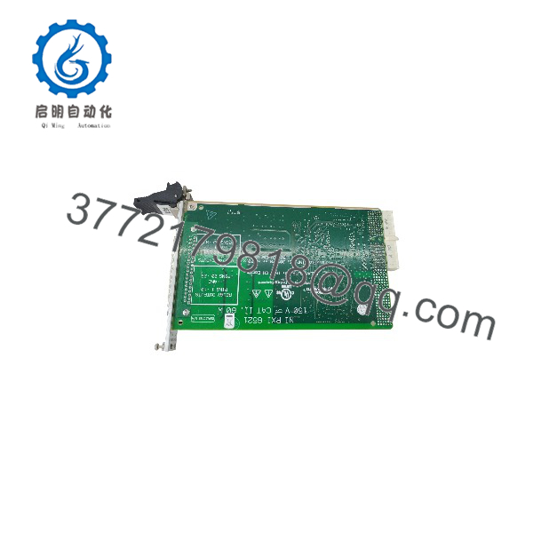
PXI-6521
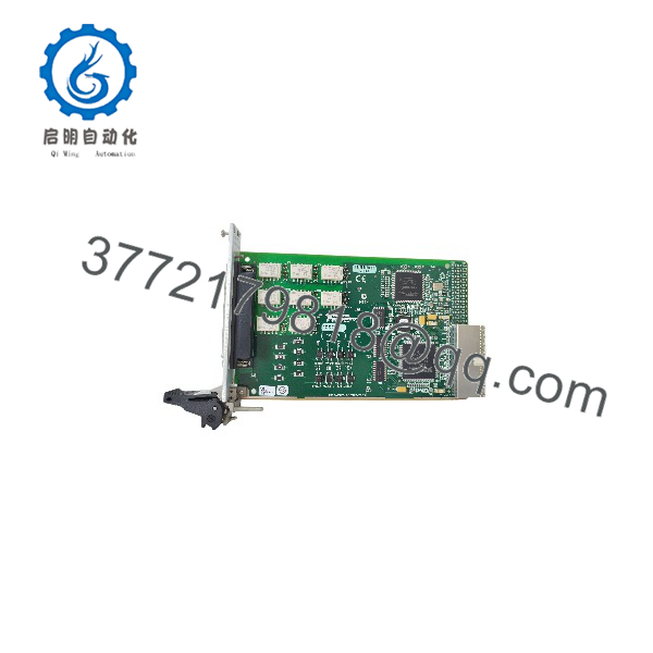
PXI-6521
Detailed Product Overview
Isolated Digital Input Architecture
The PXI-6521 provides eight optically isolated digital input channels for acquiring industrial control signals. Each input is bipolar and isolated from the other input channels. The differential input voltage must remain within the specified ±30 VDC range, even when the terminals operate at an elevated common-mode voltage relative to earth.
This architecture is useful when integrating signals from separate control circuits, monitoring external switching states, or collecting digital status information in a PXI-based test system. The input current depends on the applied signal voltage, reaching a specified maximum of 12.5 mA per channel at 30 V.
The input propagation delay is typically 45 µs. Engineers designing event-monitoring applications should account for this delay when establishing timing requirements and coordinating input transitions with other measurement activities.
Electromechanical Relay Outputs
The eight output channels use non-latching electromechanical relays. Three channels provide SPDT Form C contacts, which include normally open and normally closed contact paths. The remaining five channels use SPST Form A contacts.
The relay outputs support switching up to 150 VAC or 150 VDC under Measurement Category II conditions. The maximum switching power is 60 W or 60 VA, and the PXI-6521’s specified maximum current is 2 A per channel. These limits apply together: a load must satisfy the voltage, current, and switching-power ratings rather than relying on the maximum current rating alone.
The relays are non-latching, so their contact states depend on coil energization. By default, the relays are de-energized at power-up and power-off. Programmable power-up states allow the output behavior to be configured, with a specified 400 ms response time for those power-up settings.
Fault Handling and Digital Monitoring
The PXI-6521 includes digital filtering, change detection, programmable power-up states, and a digital I/O watchdog. These functions support input-event monitoring and defined output behavior under specified software or system fault conditions.
The watchdog can be configured to place outputs into a predetermined state when the watchdog condition is triggered. This feature should be treated as a hardware output-management mechanism, not as a substitute for a separately engineered safety instrumented function.
For applications involving contactors, solenoids, or other inductive loads, external suppression and load-protection measures should be selected according to the load characteristics and relay specifications.
System Compatibility & Integration Requirements
| Item / Dependency | Verified Compatibility or Requirement | Practical Note |
|---|---|---|
| Chassis | PXI-compatible chassis | Confirm the chassis provides the required PXI slot and power capacity. |
| Bus interface | PXI Hybrid | Check slot and chassis compatibility before installation. |
| Driver software | NI-DAQ 7.5 or later is specified in the NI 6520/6521 User Guide | Confirm the installed driver supports the target operating system and application environment. |
| I/O connector | 37-pin keyed male D-SUB | Use a compatible keyed cable and accessory. |
| Terminal accessories | TB-2621 or CB-37F-HVD | Select the terminal accessory according to mounting and voltage requirements. |
| Input signals | Eight optically isolated bipolar digital inputs | Maintain the specified differential input voltage and isolation limits. |
| Output loads | Eight non-latching relay outputs | Evaluate switching voltage, current, power, and load characteristics together. |
| Signal cabling | Shielded cable for documented EMC compliance conditions | Select a suitable cable length and routing arrangement. |
Dimensions, Mounting & Connection Notes
- Physical dimensions: 160 × 100 mm.
- Weight: 150 g.
- Connector: 37-pin keyed male D-SUB.
- Operating environment: Indoor use, 0 to 55 °C, 10–90% relative humidity, noncondensing.
- Terminal accessory options: TB-2621 front-mounting terminal block and CB-37F-HVD DIN-rail terminal block.
- Electrical safety: The device is rated for Measurement Category II, with a maximum working voltage of 150 V channel-to-earth and channel-to-channel.
The PXI-6521 must be installed in a properly configured PXI chassis with the required filler panels in place. Disconnect power from signal lines before connecting or disconnecting wiring. When hazardous voltages are present, all connected signals must be treated as potentially hazardous, and external wiring must be insulated appropriately.
Do not connect the module to Measurement Category III or IV circuits, or to mains circuits exceeding its specified voltage rating.
FAQ
What is the NI PXI-6521?
The NI PXI-6521 is an isolated digital I/O module with eight optically isolated digital inputs and eight electromechanical relay outputs for PXI-based measurement and control systems.
How many input and output channels does it provide?
It provides 16 channels in total: eight digital inputs and eight relay outputs. The relay outputs comprise three SPDT Form C channels and five SPST Form A channels.
What input voltage does the PXI-6521 support?
The differential input voltage range is −30 VDC to +30 VDC. The input signal must remain within this range while meeting the module’s channel-to-earth and isolation limits.
What is the maximum relay switching voltage?
The relay contacts support up to 150 VAC or 150 VDC under Measurement Category II conditions. Maximum switching power is 60 W or 60 VA, with a specified maximum current of 2 A per channel for the PXI version.
Which connector and terminal accessories are suitable?
The module uses a 37-pin keyed male D-SUB connector. Compatible accessory options include the TB-2621 terminal block and CB-37F-HVD DIN-rail terminal block.
Does the PXI-6521 support watchdog functions?
Yes. Its digital I/O watchdog can be configured to place outputs in a predetermined state when a watchdog condition is triggered. The intended fault response should be evaluated as part of the overall control-system design.
What should be checked before installing the module?
Confirm PXI chassis compatibility, driver support, connector keying, input voltage limits, relay contact ratings, isolation requirements, and the suitability of the selected cables and terminal accessories.