WhatsApp: +86 16626708626
 Email:
 Phone: +86 16626708626
Description
Core Product Summary
The National Instruments PXI-7340 is a programmable motion controller for coordinating up to four independent or coordinated axes using servo motors or stepper motors. It combines trajectory generation, motion sequencing, feedback processing, and dedicated motion I/O in a PXI-based automation or test system. Servo axes operate in closed-loop mode, while stepper axes support open-loop or closed-loop operation.
The controller provides ±10 V analog command outputs for servo control, step/direction or clockwise/counterclockwise digital commands for stepper drives, four analog input channels, and 32 bits of general-purpose digital I/O. Encoder feedback, limit and home switch inputs, trigger signals, and breakpoint outputs support motion sequencing and machine-interface design. Integration requires a compatible PXI chassis, NI-Motion driver software, suitable motion cabling, and drive or interface hardware matched to the motor and signal configuration. The external motion and digital I/O connections use high-density 68-pin female VHDCI connectors.
Key Technical Specifications
| Parameter | Specification |
|---|---|
| Manufacturer | National Instruments (NI) |
| Model | PXI-7340 |
| Product type | Programmable motion controller |
| System interface | PXI |
| Motion axes | Up to 4 independent or coordinated axes |
| Motor types | Servo and stepper motors |
| Servo control | Closed-loop |
| Stepper control | Open-loop or closed-loop |
| Servo command output | ±10 V analog |
| Stepper command output | Step/direction or CW/CCW |
| User analog inputs | 4 channels, 12-bit resolution |
| Analog input range | ±10 V |
| General-purpose digital I/O | 32 bits |
| Digital I/O configuration | Four 8-bit ports, programmable direction and polarity |
| Digital output drive | 24 mA source or sink per output circuit |
| Encoder feedback | Quadrature encoder inputs for up to four axes |
| Motion feedback and control signals | Encoder, limit, home, trigger, breakpoint, and inhibit signals |
| Hardware synchronization | RTSI bus, with 8 trigger lines |
| Servo PID update interval | 62.5 µs to 5 ms per sample |
| Four-axis servo PID update interval | 250 µs total |
| Stepper trajectory update interval | 62.5 to 500 µs per sample |
| Motion I/O connector | 68-pin female VHDCI |
| Digital I/O connector | 68-pin female VHDCI |
| Maximum power requirement | +5 VDC at 1 A; +12 VDC at 30 mA |
| Operating temperature | 0 to 55 °C |
| Operating humidity | 10–90% RH, noncondensing |
| Maximum operating altitude | 2,000 m |
Detailed Product Overview
Multi-Axis Motion Control
The PXI-7340 combines trajectory generation, motion sequencing, feedback processing, and I/O handling in a dedicated motion controller. It can coordinate up to four axes, allowing machine builders to manage multiple servo or stepper axes within one controller.
The controller’s onboard processing architecture separates time-critical motion functions from host communication and application-level commands. This allows trajectory execution and feedback processing to continue under the controller’s motion-control architecture rather than relying exclusively on host-PC timing.
For applications requiring coordinated movement, the controller supports synchronized multi-axis operation. The appropriate axis configuration, feedback source, drive interface, and motion profile must be selected for the actual machine mechanics.
Servo Control and Feedback
Servo axes operate in closed-loop mode using quadrature encoder or analog feedback. The controller generates analog command signals over a ±10 V range for compatible servo drives or other supported servo devices.
The programmable PID and PIVff control modes provide options for configuring position and velocity response. Dual-loop control is also supported for appropriate feedback arrangements. Feedforward terms, integration limits, derivative sampling, and velocity-feedback gains provide additional control parameters.
The specified PID update interval ranges from 62.5 µs to 5 ms per sample. The four-axis update interval is 250 µs total. These figures describe controller update timing, not a guaranteed mechanical positioning accuracy or complete machine response time.
Stepper Motor Control
The PXI-7340 supports stepper axes in open-loop or closed-loop operation. Digital command outputs can use step/direction or clockwise/counterclockwise signaling, depending on the configured drive interface.
Full-step, half-step, and microstepping applications are supported. Closed-loop stepper configurations can use encoder or analog feedback for position and velocity feedback.
The controller supports programmable trajectory parameters, including position, velocity, and acceleration/deceleration. Drive pulse requirements, motor characteristics, feedback scaling, and mechanical limits must be configured together to achieve the intended motion.
Motion I/O and Machine Synchronization
The motion I/O connector carries signals required for axis control, including encoder feedback, limit and home switches, trigger inputs, breakpoint outputs, and inhibit signals. These signals allow the controller to respond to machine events and coordinate motion with external equipment.
The separate digital I/O connector provides 32 configurable digital I/O bits arranged as four 8-bit ports. Two pulse-width modulation outputs are also available. The RTSI connector supports hardware timing and trigger exchange with compatible National Instruments devices.
The controller does not provide isolation between its circuits. External interfaces, grounding, cable shielding, and signal voltage limits therefore require careful attention when connecting the controller to drives, sensors, or other equipment.
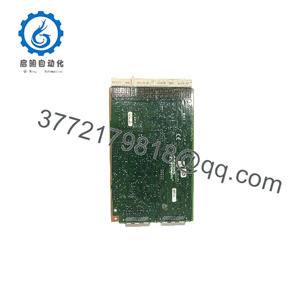
PXI-7340
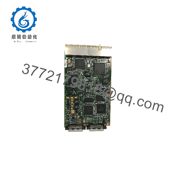
PXI-7340
System Compatibility & Integration Requirements
| Item / Dependency | Verified Compatibility or Requirement | Practical Note |
|---|---|---|
| Chassis | Compatible PXI system | Verify the available slot and chassis installation requirements. |
| Motion driver | NI-Motion 6.1 or later, as specified in the user manual | Check the driver version against the host operating system and application environment. |
| Programming environments | LabVIEW, LabWindows/CVI, C/C++, and other supported NI-Motion API environments | Confirm the software version and driver integration before commissioning. |
| Servo drive interface | Compatible servo device accepting ±10 V command signals | Match command polarity, feedback scaling, and drive configuration. |
| Stepper drive interface | Compatible drive accepting step/direction or CW/CCW commands | Confirm pulse requirements and command polarity. |
| Encoder feedback | Compatible quadrature encoder or supported analog feedback | Verify signal wiring and feedback configuration for each axis. |
| Motion cabling | 68-pin female VHDCI motion I/O connector | Use a compatible cable or interface accessory. |
| Digital I/O cabling | Separate 68-pin female VHDCI connector | Select cabling and termination for the required digital signals. |
| Motion interface accessories | Universal Motion Interface (UMI), suitable drive amplifiers, and connector blocks are available as accessory categories | Select the interface according to the connected drive and wiring architecture. |
| Synchronization | RTSI bus | Verify signal routing when coordinating motion with other compatible NI hardware. |
Dimensions, Mounting & Connection Notes
- Mounting: Install in an open, compatible PXI expansion slot.
- Motion I/O connector: 68-pin female VHDCI.
- Digital I/O connector: 68-pin female VHDCI.
- RTSI connection: Dedicated connector for supported synchronization and trigger signals.
- Power requirements: +5 VDC at up to 1 A and +12 VDC at up to 30 mA.
- Operating environment: 0 to 55 °C and 10–90% relative humidity, noncondensing.
- EMC installation: Use shielded cables and accessories to meet the documented electromagnetic compatibility conditions.
The motion I/O and digital I/O connectors serve different functions. The motion connector carries axis-control and feedback signals, while the digital connector carries the 32-bit general-purpose digital I/O interface. Confirm connector pin assignments before wiring.
Power down the controller system and connected equipment before connecting or disconnecting motion and auxiliary digital I/O cables. The controller’s signals are not isolated, so do not connect external circuits without checking their voltage levels, grounding arrangement, and electrical compatibility.
FAQ
What is the NI PXI-7340?
The NI PXI-7340 is a programmable four-axis motion controller for servo and stepper motor applications in PXI-based automation and test systems.
How many axes can the PXI-7340 control?
It supports up to four independent or coordinated axes. The available control modes include closed-loop servo control and open-loop or closed-loop stepper control.
Does the PXI-7340 support analog servo drives?
Yes. Servo axes provide ±10 V analog command outputs for compatible servo drives. The drive’s command input requirements and the controller’s feedback configuration must be matched during integration.
What feedback signals does the controller support?
The controller supports quadrature encoder feedback and analog feedback for applicable motion-control configurations. Its motion I/O also includes limit, home, trigger, breakpoint, and inhibit signals.
How many general-purpose digital I/O points are available?
The controller provides 32 digital I/O bits arranged as four 8-bit ports. Direction and polarity are programmable, and the output circuits support 24 mA source or sink operation.
Which software is required?
The NI 7340 user manual specifies NI-Motion 6.1 or later. Programming options include LabVIEW, LabWindows/CVI, C/C++, and supported environments that can use the NI-Motion API. Actual operating-system and software compatibility must be assessed for the installed system.
Can the PXI-7340 synchronize with other NI devices?
Yes. The controller supports the RTSI bus, which provides trigger and timing connections for supported National Instruments hardware.
What should be checked before replacing or integrating a PXI-7340?
Confirm the PXI chassis, NI-Motion driver environment, motor-drive command interface, encoder wiring, limit-switch configuration, digital I/O requirements, and motion cable pin assignments. A matching controller model alone does not establish that the complete motion system is configured correctly.