
 WhatsApp: +86 16626708626
 Email:
  Phone: +86 16626708626
Description
Key Technical Specifications
| Parameter | Value |
|---|---|
| Manufacturer | OKOS |
| Model | AL8XGTE-3 |
| Product Family | AL8xGTE high-speed digitizers |
| Product Type | PCI Express high-speed digitizer / data acquisition board |
| Host Bus | PCI Express x1 |
| Acquisition Channels | 1 analog input channel |
| ADC Resolution | 8 bits |
| Maximum Sampling Rate | 3 GS/s |
| Selectable Sampling Rates | 1, 1.5, 2, or 3 GS/s |
| Sampling Interval at Maximum Rate | 333 ps |
| Analog Input Coupling | DC coupled |
| Input Termination | 50 Ω |
| Input Bandwidth | Greater than 1 GHz |
| Programmable Input Range | 125 mV p-p to 2 V p-p |
| Available Input Ranges | 125 mV, 250 mV, 500 mV, 1 V, and 2 V peak-to-peak |
| Onboard Memory Architecture | Dual-port acquisition buffer |
| Onboard Memory Options | 512 MSamples to 2 GSamples; verify installed memory option from board label |
| Data Transfer | PCI Express DMA transfer |
| Recording Behavior | Supports acquisition while previously captured data transfers to the host |
| Trigger Sources | Software, analog input, external TTL, and position-derived trigger sources |
| Trigger Capability | Configurable trigger modes for transient acquisition |
| Software | Evaluation oscilloscope program; drivers and DLLs for user applications |
| Typical Use | Ultrasonic microscopy, nondestructive testing, pulsed ultrasonics, high-speed transient capture, laboratory instrumentation, and custom industrial DAQ |
| Host Requirement | Compatible PCI Express x1 or mechanically compatible larger PCIe slot |
| Lifecycle Note | Verify installed memory size, driver version, FPGA/firmware revision, OS support, trigger connector configuration, and included SDK before ordering |
The OKOS AL8XGTE-3 is a single-channel, 8-bit PCI Express digitizer with sampling rates up to 3 GS/s. Published product information identifies DC-coupled 50 Ω analog input, more than 1 GHz analog bandwidth, programmable input ranges from 125 mV p-p to 2 V p-p, selectable sampling rates from 1 to 3 GS/s, and dual-port onboard memory for concurrent capture and data transfer.
Product Introduction
The OKOS AL8XGTE-3 is a high-speed PCI Express digitizer designed to capture short-duration analog events that ordinary PLC analog modules, oscilloscopes, and low-speed DAQ cards cannot resolve. Its single 8-bit channel samples at up to 3 GS/s, making it suitable for ultrasonic microscopy, pulse-echo testing, transient measurement, high-frequency sensor evaluation, and custom test equipment.
The board uses a DC-coupled 50 Ω input and programmable ranges from 125 mV p-p to 2 V p-p. It also supports software, analog, external TTL, and position-based triggering. Confirm the actual onboard-memory option, driver/SDK version, host PCIe compatibility, input amplitude, trigger wiring, and operating-system support before replacing a failed card or building it into a new test station.
Troubleshooting Quick Reference
| Symptom | Possible Cause | Relevance to this Part | Quick Check Method | Recommendation |
|---|---|---|---|---|
| Board is not detected by the host PC | Board not fully seated, incompatible PCIe slot, BIOS setting, missing driver, failed board | ⚠️ Medium | Shut down the PC, reseat the board, inspect PCIe contacts, test another compatible PCIe slot, and check Device Manager | Confirm motherboard and driver compatibility before replacing the AL8XGTE-3 |
| Acquisition software opens but no waveform appears | No input signal, wrong trigger source, trigger threshold incorrect, cable fault, input range too large | ⚠️ Medium | Inject a known signal from a calibrated generator; select free-run or software trigger; verify 50 Ω cable continuity | Start with a known-good signal and free-run acquisition before troubleshooting trigger logic |
| Board triggers but waveform is clipped | Input signal exceeds selected range, DC offset too high, wrong input-range setting | ❌ Low | Measure the signal with a calibrated oscilloscope; reduce source amplitude or select a larger p-p range | Keep the analog input within the selected 125 mV p-p to 2 V p-p range |
| Captured waveform is too small or noisy | Input range too large, poor 50 Ω termination, cable mismatch, external EMI, ground-loop issue | ⚠️ Medium | Select the smallest range that does not clip; use a short 50 Ω coax cable; compare against a known source | Treat the input as a 50 Ω high-frequency signal path. Do not use ordinary unshielded sensor wiring |
| Data is distorted or amplitude is wrong | Source impedance mismatch, cable reflections, non-50 Ω source, incorrect calibration, input overload | ⚠️ Medium | Verify source impedance and cable type; use proper 50 Ω feed-through termination where required; compare with a reference oscilloscope | Correct signal integrity first. High-speed DAQ problems are often cabling problems, not card failures |
| External TTL trigger does not fire | Wrong trigger connector, insufficient threshold, incorrect polarity or edge, cable fault, trigger mode mismatch | ⚠️ Medium | Check TTL level with an oscilloscope; confirm trigger source, slope, threshold, delay, and trigger connector pinout in the software/manual | Validate the trigger signal independently before replacing the board |
| Analog trigger is unreliable | Trigger threshold too close to noise, signal amplitude too low, ringing, incorrect coupling assumptions | ⚠️ Medium | Observe the input on a high-bandwidth scope; move the threshold away from baseline noise and ringing | Use external TTL triggering when repeatability matters and a clean trigger source is available |
| Samples are lost during long acquisitions | Insufficient onboard memory, host PCIe bottleneck, software buffering limit, disk-write latency | ⚠️ Medium | Check installed memory option, capture record length, DMA status, host CPU load, and storage throughput | Reduce record length or acquisition rate, improve host performance, or verify the correct memory-equipped board |
| Software captures data once, then hangs | Driver mismatch, unsupported operating system, old SDK, DMA conflict, host power-management issue | ⚠️ Medium | Check driver and SDK versions, Windows event logs, PCIe power-management settings, and test on a validated host | Use the approved driver stack. Do not assume a current OS supports legacy DAQ drivers without validation |
| Board shows random trigger timing | External noise, trigger cable ground problem, floating source, improper shielding | ❌ Low | Use a short shielded trigger cable, establish a single reference ground, and test with an isolated signal generator | Correct grounding and trigger integrity before replacing the digitizer |
| Data-transfer rate is slow | PCIe lane negotiation issue, host chipset limitation, excessive software processing, DMA not enabled | ⚠️ Medium | Check PCIe link status, host slot configuration, CPU utilization, and application settings | Install the board in a compatible direct motherboard PCIe slot and minimize unnecessary processing during capture |
| Board is recognized but gives constant zero data | Input path open, front-end fault, software channel disabled, failed source, damaged connector | ⚠️ Medium | Test with a known-good sine wave at 1 V p-p; verify input connector and cable; compare against another instrument | If a verified 50 Ω source produces zero data across software configurations, the analog front end may require repair or replacement |
| Board input appears damaged after test setup | Excessive voltage, DC bias beyond limits, ESD, incorrect BNC adapter, improper grounding | ✅ High | Stop testing; inspect connectors; test only with a low-amplitude known-good signal after reviewing allowable input limits | Never connect plant voltage, 24 V DC I/O, energized transducer pulser output, or a high-energy signal directly to the input |
| Replacement board is detected but does not run existing application | Different firmware, memory option, driver API mismatch, incorrect DLL version, missing license/configuration files | ✅ High | Compare original board revision, SDK/DLL version, firmware, memory capacity, and application configuration | Preserve the old PC image, installer media, and application files before card replacement |
| Waveform fidelity degrades only at high frequency | Long cable, poor connector quality, bandwidth limitation, source mismatch, probe loading | ❌ Low | Test with a short quality coax cable and calibrated source; compare low- and high-frequency amplitude response | Keep cable runs short and use proper RF-grade 50 Ω hardware for signals approaching the board bandwidth |
❗ Input-protection warning: This is a high-speed 50 Ω digitizer input—not a 24 V industrial analog input. Do not connect transmitter loops, PLC output cards, solenoid circuits, motor terminals, or unattenuated high-energy pulser outputs directly to the board.
❗ Signal-integrity warning: At 3 GS/s, a poor cable or incorrect impedance can look like a bad board. Use short 50 Ω coaxial cable, matched source impedance, proper terminations, and clean grounding. A BNC adapter chain from a field panel is not a valid high-frequency test setup.
❗ ESD warning: Install the board with the PC fully powered down and use a grounded wrist strap. The analog front end and PCIe interface are static-sensitive. Handle only by the card edges and keep protective caps on connectors until installation.
❗ Software warning: Preserve the existing driver, DLL, SDK, application configuration, and operating-system image before replacing a legacy digitizer. A physically compatible card can fail to work with an older custom application if the driver API or onboard-memory option differs.
If troubleshooting remains unresolved, provide technical support with photos of the full board label, PCIe host model, operating system, driver version, installed software version, trigger and input cable setup, input waveform details, capture settings, error messages, and a saved sample-data file.
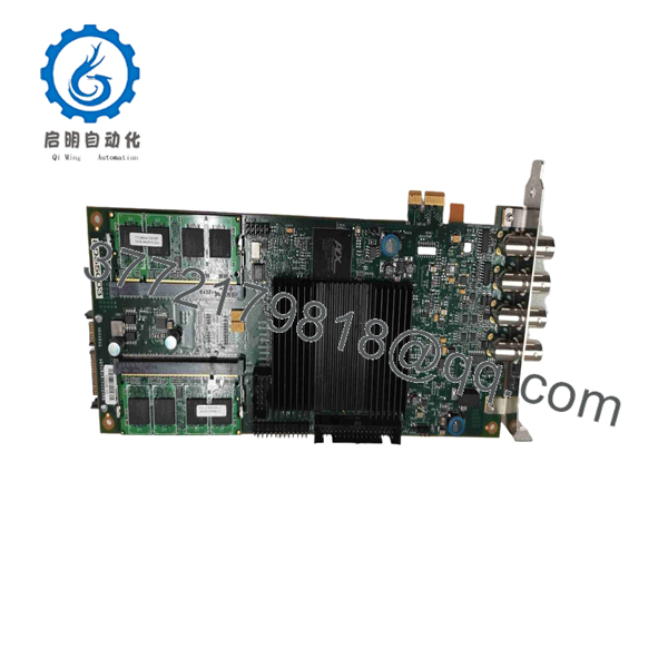
AL8XGTE-3
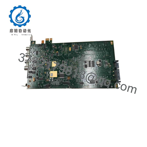
AL8XGTE-3
Frequently Asked Questions
What is the OKOS AL8XGTE-3 used for?
The AL8XGTE-3 is a high-speed data-acquisition digitizer that samples one analog waveform at up to 3 GS/s. It is intended for fast transient capture in applications such as ultrasonic microscopy, nondestructive testing, pulse measurement, laboratory instrumentation, and custom automated test systems.
How many input channels does the have?
It has one analog acquisition channel. Some reseller descriptions may mention multiple channels, but the available product documentation identifies the as a single-channel digitizer.
What is the input range?
The input range is programmable from 125 mV p-p to 2 V p-p, with published range selections of 125 mV, 250 mV, 500 mV, 1 V, and 2 V peak-to-peak. Set the smallest range that captures the full waveform without clipping to get the best use of the 8-bit converter resolution.
Can I connect a 4–20 mA transmitter or 24 V signal directly to it?
No. The board expects a DC-coupled, 50 Ω, high-speed analog signal. A 4–20 mA loop or 24 V industrial signal requires a correctly designed conditioning circuit, attenuator, isolation stage, and bandwidth review before connection. Direct connection can damage the analog input.
What sampling rates can I select?
Published information lists selectable rates of 1, 1.5, 2, and 3 GS/s. At 3 GS/s, the sample interval is approximately 333 ps. Select the rate based on the signal bandwidth, record length, trigger behavior, available onboard memory, and data-transfer requirements.
Does the support external triggering?
Yes. It supports software triggering, analog input triggering, external TTL triggering, and position-derived trigger sources. For repeatable pulsed-test applications, a clean external TTL trigger is often the simplest way to stabilize the capture timing.
Can I use the board in any PCIe slot?
It uses PCI Express x1. It should install in an available x1 slot or a mechanically compatible larger PCIe slot, subject to the PC motherboard, BIOS, operating system, driver, and chassis clearance. Use a direct motherboard slot when possible; low-quality risers and unpowered expansion systems can create DMA or link-stability problems.
Will the existing acquisition software work after replacing the board?
Not automatically. Verify the driver version, DLL/API version, FPGA/firmware revision, onboard-memory option, and operating-system compatibility. Save the original system image and application configuration first. This matters most when the digitizer runs a custom ultrasonic or inspection application written for an older SDK.
It should be treated as a specialized, legacy high-speed acquisition card with availability dependent on surplus inventory and support for older host operating systems. For a critical system, keep a tested spare, original drivers, SDK installer, application binaries, calibration records, PCIe host image, and cable/trigger diagrams.
What condition should I request for a production or laboratory spare?
Request New Original / New Surplus with photos of the full board label, input connector, PCIe edge connector, antistatic packaging, and included accessories. For Refurbished (tested) stock, require a report covering PCIe enumeration, all selectable sampling rates, input-range checks, external and software trigger response, DMA transfer, onboard-memory verification, waveform capture with a calibrated 50 Ω source, and sustained acquisition testing. Request the driver/SDK media, actual stock confirmation, warranty, return terms, and lead time before purchase.



