
 WhatsApp: +86 16626708626
 Email:
  Phone: +86 16626708626
Description
Key Technical Specifications
| Parameter | Value |
|---|---|
| Manufacturer | Okuma Corporation |
| Part Number | E4809-770-065-B |
| Alternative Reference | E4809770065B |
| Product Type | Servo drive / control PCB |
| Board Family | E4809 |
| SVC Designation | SVC-II |
| Application | Okuma CNC servo systems |
| Reported Board Classification | SVC-II Type A / Type B — supplier documentation conflicts |
| Compatible Drive Family | Legacy Okuma servo amplifier systems, including BLII-D references |
| Construction | Multi-layer industrial PCB assembly |
| Installation | Internal CNC servo-drive/control assembly |
| Weight | Approximately 1.84 lb / 0.83 kg according to one distributor |
| Manufacturer Status | Discontinued |
| Replacement Strategy | Exact part-number replacement preferred |
The available documentation does not provide enough authoritative information to state a definitive board-level supply voltage, current rating, connector pinout, processor specification, or firmware revision. Those values should not be guessed from third-party listings. Radwell identifies the board as a servo amplifier PCB and SVC-II board, while other sources associate it with Okuma BLII-D servo-drive assemblies.
Product Introduction
The Okuma E4809-770-065-B is a legacy CNC servo-drive PCB used within Okuma motion-control hardware. Available technical references identify it as an SVC-II board associated with servo amplifier systems and closed-loop axis control.
This is not a standalone PLC or general-purpose I/O module. Replacement work must match the complete E4809-770-065-B part number and the installed servo-drive assembly. Do not substitute another
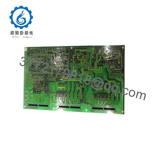
E4809-770-065-B
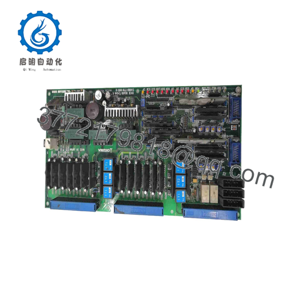
E4809-770-065-B
E4809 revision solely because its connector arrangement appears similar.
Installation & Configuration Guide
Stage 1: Pre-Installation Preparation — About 10–15 Minutes
⚠️ Safety First
- Notify machine operations and establish a controlled maintenance window.
- Stop the CNC machine using the normal shutdown procedure.
- Apply lockout/tagout (LOTO) to the machine and servo-drive power sources.
- Wait for the manufacturer’s specified DC-bus discharge period.
- Verify the DC bus is at a safe voltage with a properly rated multimeter before opening the drive.
- Do not rely solely on the CNC display or drive indicator lamps to establish zero energy.
Tools Required
- ESD wrist strap
- Properly rated digital multimeter
- Phillips screwdriver
- Insulated hand tools where required
- Wire labels
- Smartphone or camera
- Service documentation for the specific Okuma machine and servo amplifier
Data Backup
Before removing the board:
- Record the complete machine model and serial number.
- Record the servo amplifier model and serial number.
- Photograph the E4809-770-065-B board from both accessible sides.
- Photograph all ribbon cables and plug connectors.
- Record connector positions and cable routing.
- Back up CNC parameters and servo parameters according to the machine’s maintenance procedure.
- Record any drive alarms present before shutdown.
⚠️ Do not erase or alter servo parameters while diagnosing a hardware fault. A board replacement and a parameter change are two separate variables.
Stage 2: Removing the Old Module — About 10 Minutes
- Confirm the machine is electrically isolated.
- Verify the DC bus has discharged to the manufacturer’s specified safe level.
- Open the servo-drive enclosure according to the Okuma service procedure.
- Photograph every connector before disconnecting it.
- Label cables if their existing markings are unclear.
- Disconnect the board connectors without pulling on the wires.
- Release the PCB retaining hardware.
- Remove the board while supporting it evenly.
- Inspect the backplane and connectors for contamination, corrosion, bent contacts, or heat damage.
- Compare the removed board’s identification label with the replacement.
⚠️ Keep the failed board. Its component layout, revision markings, connector configuration, and diagnostic evidence may be needed if the replacement does not resolve the original alarm.
Stage 3: Installing the New Module — About 10 Minutes
- Put on the grounded ESD wrist strap.
- Confirm the replacement is marked E4809-770-065-B.
- Compare the board physically with the original before inserting it.
- Check connector locations and board revision markings.
- Do not force a connector that does not align naturally.
- Insert the PCB into its correct guides or mounting position.
- Secure the retaining screws or hardware evenly.
- Reconnect each cable according to the photographs taken during removal.
- Check that every connector is fully seated.
- Inspect the board for trapped wires, loose hardware, or foreign objects.
Self-Checklist
- Exact E4809-770-065-B part number verified
- Board revision compared
- Connector positions matched
- Ribbon cables correctly seated
- Mounting hardware secured
- No loose screws or foreign material
- ESD controls maintained
Stage 4: Power-On & Testing — About 15–30 Minutes
- Perform a complete visual and electrical inspection before energizing the drive.
- Verify that all covers and protective barriers required for operation are installed.
- Restore power according to the Okuma machine service procedure.
- Observe the CNC and servo amplifier diagnostic indicators.
- Check whether the original servo alarm has cleared.
- Confirm communication between the CNC control and servo amplifier.
- Execute the manufacturer’s servo initialization or diagnostic procedure.
- Test the affected axis at low speed under controlled conditions.
- Check encoder/feedback behavior.
- Run a controlled reference or positioning test before returning the machine to production.
⚠️ Do not immediately command full-speed axis motion after replacing a servo-control PCB. First establish that the drive initializes correctly and that feedback polarity, axis identification, and servo response are normal.
Technical Pitfalls & Survival Guide
1. ⚠️ Exact Revision Mismatch
This is the first thing I would check. Third-party databases disagree on whether this exact part number is classified as SVC-II Type A or Type B. That alone is enough reason not to order by the description “SVC-II board” without matching the complete part number.
2. ⚠️ Do Not Assume the Board Is the Root Cause
A servo communication alarm can originate from the control board, power section, gate-drive circuitry, feedback circuit, cabling, or the CNC control. A March 2026 repair report specifically describes an board associated with a BLII-D7550A servo drive where one axis exhibited a communication fault and abnormal gate-drive behavior. That is useful diagnostic context, but it does not establish that every similar alarm is caused by this PCB.
3. ⚠️ Parameter Retention
A PCB replacement does not automatically mean the machine’s servo parameters are correct. Back up the CNC parameters before beginning work and compare the post-replacement configuration against the machine’s documented values.
4. ⚠️ Connector and Backplane Condition
A replacement PCB can appear defective when the actual problem is an oxidized connector, damaged contact, loose ribbon cable, or contaminated backplane. Inspect the mating interfaces before condemning the replacement board.
5. ⚠️ ESD and DC-Bus Energy
This board operates inside a servo-drive environment. ESD can damage control electronics, while residual DC-bus energy can present a serious electrical hazard. Use the machine-specific Okuma service procedure for discharge verification rather than relying on a generic five-minute waiting period.
Frequently Asked Questions (FAQ)
What is the Okuma ?
It is an Okuma CNC servo-drive PCB, commonly identified as an SVC-II board. Industrial suppliers associate it with legacy Okuma servo amplifier systems and CNC motion-control equipment.
Is obsolete?
Available supplier documentation identifies the part as discontinued. Remaining units are generally sourced from surplus, unused legacy inventory, refurbished stock, or repair/exchange channels.
Is the same as E4809770065B?
Yes, E4809770065B is used as an alternative formatting of the same part-number string in multiple supplier records. Nevertheless, the complete physical label should be checked before purchase.
Is it SVC-II Type A or Type B?
This requires caution. Several suppliers identify as SVC-II Type A, while other documentation labels the same part number SVC-II Type B. Because the descriptions conflict, I would not use “Type A” or “Type B” alone as a purchasing criterion. Match , the physical board, revision markings, and the servo amplifier application.
Can I install this board without backing up CNC parameters?
I would not. Even when the PCB itself does not contain the machine’s primary CNC program, a servo-control replacement should be performed with a current parameter backup available. If the machine does not initialize correctly afterward, you need the original parameter state available for controlled troubleshooting.
What condition should I specify when purchasing this board?
Specify the condition explicitly: New Original / New Surplus, Never Used Original Packaging, or Refurbished (tested). Current market listings show materially different condition categories for this part. For example, Radwell lists never-used and refurbished variants separately.
Can the board be functionally tested before shipment?
Yes, but the test must be meaningful. A simple continuity check is not enough for a servo-control PCB. A proper test should use a compatible Okuma servo-drive test setup or an appropriate machine platform and verify power-up behavior, drive communication, diagnostics, and relevant servo-control functions. One specialist repair source reports testing this part through Okuma servo-drive repair procedures, while another reports successful repair work on boards.



