
 WhatsApp: +86 16626708626
 Email:
  Phone: +86 16626708626
Description
Key Technical Specifications
| Parameter | Specification |
|---|---|
| Manufacturer | Pacific Scientific |
| Model | 6445-001-K-N |
| Product Family | 6410 Stepper Drives |
| Product Type | Microstepping indexer / stepper drive |
| Input Voltage | 120/240 VAC ±10% / −15% |
| Input Frequency | 50/60 Hz |
| Input Phase | Single phase |
| Nominal DC Bus | 66 VDC |
| Drive Circuit | Two-phase bipolar, chopper current regulated |
| Maximum Phase Current | 5.0 A RMS |
| Microstep Current | 3.5 A RMS |
| Peak Current | 7.1 A peak |
| Step Resolution | 200–50,000 steps/revolution |
| Programmable Inputs | 16 open-collector logic inputs |
| Programmable Outputs | 12 open-collector outputs |
| Fault Output | NPN open collector, 100 mA sink at 16 VDC |
| Operating Temperature | 0–50 °C at full load |
| Storage Temperature | −40–70 °C |
| Weight | Approximately 6 lb |
| Connector Kit | Included |
The 6445-001-K-N is documented as a Pacific Scientific stepper-drive/indexer package using a two-phase bipolar chopper-current-regulated architecture. Technical listings specify 120/240 VAC single-phase input, a 66 VDC nominal bus, 5.0 A RMS maximum current, and 3.5 A RMS microstep current. Step resolution is DIP-switch selectable from approximately 200 to 50,000 steps/revolution.
The K option is significant: available Pacific Scientific configuration information identifies K as the connector-kit option, while the unit also incorporates an internal cooling fan.
Product Introduction
The Pacific Scientific 6445-001-K-N is a programmable digital stepper drive with an integrated indexer function. It controls two-phase stepper motors from a 120/240 VAC single-phase supply, with 5.0 A RMS maximum phase current and selectable microstepping for industrial positioning applications.
This model is suited to legacy machine architectures that require programmable I/O in addition to basic step-and-direction control. It provides 16 programmable inputs and 12 programmable outputs, a fault output, internal cooling fan, and the K-option connector kit. The manufacturer has discontinued the model, so exact part-number and configuration matching is important during replacement.
Installation & Configuration Guide
Stage 1 — Pre-Installation Preparation
Estimated time: 20–30 minutes
- Notify machine operations and place the axis in the approved maintenance state.
- Stop all commanded motion and apply the machine’s LOTO procedure.
- Isolate the 120/240 VAC input supply.
- Wait at least 5 minutes for stored electrical energy to discharge.
- Verify the absence of hazardous voltage with an appropriately rated multimeter.
- Wear an ESD wrist strap when handling the electronics.
- Prepare:
- PH1 screwdriver
- Digital multimeter
- Wire labels
- Camera/phone
- Approved machine schematic
- Existing Pacific Scientific configuration documentation
- Photograph every connector and configuration switch before removing the old unit.
- Record the exact model and option code.
⚠️ Critical: Do not treat 6445-001-K-N as interchangeable with visually similar 6445 or 6410-family products. The option code determines hardware configuration, including connector-kit provision.
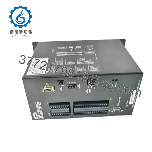
6445-001-K-N
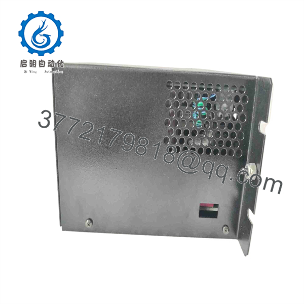
6445-001-K-N
Stage 2 — Removing the Old Module
Estimated time: 15–25 minutes
- Confirm the AC supply is isolated and verified de-energized.
- Label AC input, motor, control-I/O, and fault wiring.
- Photograph the terminal arrangement and DIP-switch positions.
- Disconnect the motor and control wiring carefully.
- Remove the AC input connections according to the approved schematic.
- Remove mounting hardware.
- Withdraw the drive without stressing the connectors.
- Inspect the cabinet for:
- Loose terminals
- Heat discoloration
- Damaged insulation
- Grounding problems
- Dust accumulation
- Blocked cooling paths
- Retain the original drive until the replacement has completed functional testing.
⚠️ The 6445 contains an internal fan and handles line-voltage input. Inspect both the cooling path and AC wiring rather than treating a drive failure as an isolated electronic problem.
Stage 3 — Installing the New Module
Estimated time: 25–35 minutes
- Compare the replacement label with the removed unit.
- Confirm 6445-001-K-N exactly.
- Verify that the connector kit configuration matches the installation.
- Mount the drive securely with adequate clearance for ventilation.
- Confirm the motor’s rated current and winding configuration.
- Set the applicable current and microstepping switches according to the approved 6445 documentation.
- Match programmable-input/output assignments to the machine schematic.
- Reconnect:
- 120/240 VAC input
- Motor phases
- Programmable inputs
- Programmable outputs
- Fault output
- Protective grounding
- Perform a point-to-point wiring check before energization.
⚠️ Do not guess the motor-current setting. The documented 5.0 A RMS maximum and 3.5 A RMS microstep-current values are drive capabilities, not a universal setting for every connected motor.
Stage 4 — Power-On & Testing
Estimated time: 30–60 minutes
- With power isolated, verify AC input wiring and protective ground.
- Check for unintended shorts before applying power.
- Energize the drive under controlled conditions.
- Confirm the internal fan operates and no immediate fault condition occurs.
- Verify the controller communicates with the programmable inputs and outputs.
- Apply a low-speed index or step command.
- Confirm:
- Correct motor direction
- Stable acceleration
- Correct step resolution
- No missed steps
- No abnormal vibration
- No excessive motor heating
- Test the fault output.
- Exercise representative programmable inputs and outputs.
- Increase speed and load progressively.
- Record final switch settings, input voltage, motor current, step resolution, and test results.
⚠️ A successful power-up does not prove correct configuration. A stepper system can energize normally while the motor phase sequence, current level, step resolution, or programmable I/O mapping is wrong.
For legacy replacement QC, record incoming visual inspection, serial/part-number traceability, AC input verification, motor-phase checks, programmable I/O testing, thermal/fan operation, and controlled motion testing. Secondary-market suppliers currently advertise new, refurbished, repair, and exchange options, so the physical condition and test status should be confirmed for each unit.
Frequently Asked Questions (FAQ)
1. What is the Pacific Scientific 6445-001-K-N?
It is a programmable digital stepper motor drive with an integrated microstepping indexer. It belongs to Pacific Scientific’s 6410 stepper-drive family and operates from 120/240 VAC single-phase power.
2. What is the input voltage?
The documented input is 120/240 VAC, single phase, with a specified tolerance of approximately +10%/−15% and 50/60 Hz operation. The nominal internal bus voltage is approximately 66 VDC.
3. What is the maximum motor current?
The drive is specified for 5.0 A RMS maximum phase current, with a listed 3.5 A RMS microstep current. The correct operating current depends on the connected motor and configured drive settings.
4. What does the K in 6445-001-K-N mean?
Available configuration references identify the K option as including the connector kit. This distinguishes it from related 6445 configurations without the connector-kit option.
5. How many programmable I/O points does it have?
The documented configuration provides 16 programmable open-collector inputs and 12 programmable open-collector outputs. The outputs are rated for up to 100 mA sinking at 16 VDC in the referenced specification.
6. Is the 6445-001-K-N discontinued?
Yes. Current industrial-spares references identify the model as discontinued by the manufacturer. Secondary-market suppliers offer new-surplus, refurbished, repair, and exchange services depending on availability.
7. Can another Pacific Scientific 6445 model replace it directly?
Not automatically. Related models can differ in connector-kit configuration and other hardware options. For a direct replacement, match the complete 6445-001-K-N part number and verify motor current, input voltage, I/O configuration, step resolution, and cabinet installation requirements before commissioning.



