
 WhatsApp: +86 16626708626
 Email:
  Phone: +86 16626708626
Description
Key Technical Specifications
| Parameter | Value |
|---|---|
| Manufacturer | Denison Hydraulics / Parker |
| Part Number | 701-00610-8 |
| Alternate Format | 701006108 |
| Amplifier Model | EC01 A2O |
| Product Type | Analog proportional amplifier |
| Valve Compatibility | 4DP03E / 4DP06E |
| Solenoid Configuration | 2 solenoids |
| Solenoid Voltage | 12 VDC |
| Supply Voltage | 24 VDC nominal |
| Supply Range | 20–32 VDC |
| Board Consumption | Approx. 200 mA + solenoid current |
| Output | 24 V PWM |
| Maximum Output Current | Approx. 2,700 mA nominal specification; selectable maximum-current range up to 3,000 mA |
| Factory Nominal Current | 2,200 mA |
| Factory Minimum Current | 0 mA |
| Dither Frequency | 150 Hz factory setting |
| Selectable Dither | 100 / 150 / 250 Hz |
| Dither Amplitude | 0–300 mA |
| Command Inputs | 0–±5 V, 0–±10 V, 0–±20 mA, 4–20 mA |
| Input Impedance | 100 kΩ for voltage inputs; 100 Ω for current inputs |
| Connector | DIN 41612 Type F, 48-pin |
| Card Dimensions | 160 × 100 mm Eurocard |
| Front Plate | 3U / 8HP, 128.5 × 40.4 mm |
| Weight | Approx. 250 g |
| Operating Temperature | 0 to +70 °C |
| Storage Temperature | −40 to +125 °C |
| Protection | Reverse-polarity and solenoid short-circuit protection |
Parker’s technical documentation specifies a 20–32 VDC supply, DIN 41612 Type F 48-pin connector, Eurocard dimensions, and selectable command-input ranges. The same document specifies selectable dither frequencies and maximum-current settings.
The manufacturer’s reference table associates 701-00610-8 with 4DP03E/4DP06E, 12 V solenoids, with 150 Hz dither, 150 mA dither amplitude, 2,200 mA nominal current, and 0 mA minimum current.
Important distinction: the amplifier accepts a 24 VDC supply, but the referenced valve configuration uses 12 V solenoids. Do not confuse the amplifier supply voltage with the solenoid voltage.
Product Introduction
The Denison 701-00610-8 is an EC01 A2O analog proportional amplifier card designed to control two 12 V solenoids on Denison 4DP03E and 4DP06E proportional directional valves. It converts voltage or current command signals into controlled PWM solenoid current.
The card provides adjustable ramp functions, dither, minimum current, and maximum current. It accepts common PLC analog-output signals, including ±10 V and 4–20 mA. This makes it suitable for hydraulic motion-control systems where the controller commands proportional valve position or flow.
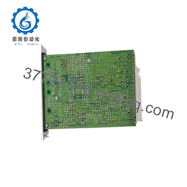
701-00610-8
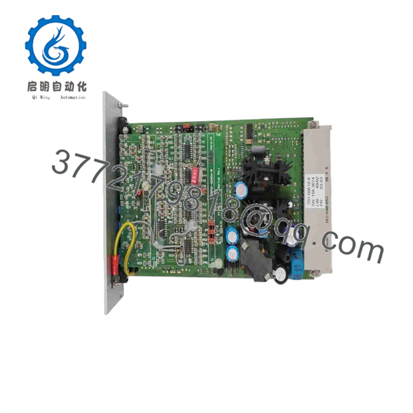
701-00610-8
Installation & Configuration Guide
Estimated replacement time: 30–60 minutes for an experienced hydraulic controls technician, excluding valve commissioning.
Stage 1: Pre-Installation Preparation
⚠️ Safety First
- Stop the hydraulic machine using the approved shutdown sequence.
- Lock out electrical power and isolate hydraulic pressure.
- Bleed stored hydraulic pressure before opening the control cabinet or valve manifold.
- Verify zero pressure with the appropriate pressure gauge or test point.
- Wait for electrically stored energy to discharge.
- Wear an ESD wrist strap when handling the amplifier card.
Tools Required
- ESD wrist strap
- Digital multimeter
- Small screwdriver set
- Wire labels
- Camera/smartphone
- Appropriate hydraulic pressure test equipment
- Configuration documentation
Data Backup
Before removing the existing amplifier:
- Photograph the front panel.
- Record 701-00610-8 and any revision markings.
- Photograph all DIP switches.
- Photograph jumpers JP4/JP5 and other configuration links.
- Record command-signal type.
- Record I_MAX and I_MIN settings.
- Record ramp settings.
- Record dither frequency and amplitude.
- Identify the controlled valve and solenoid voltage.
⚠️ Take a photograph of every DIP-switch and jumper position before removing the card. Parker’s manual explicitly warns that incorrect jumper/DIP settings can prevent the amplifier from generating the correct output current.
Stage 2: Removing the Old Module
- Verify electrical isolation.
- Verify hydraulic pressure has been relieved.
- Label the command, current-monitor, and control connections.
- Disconnect the 48-pin DIN connector carefully.
- Release the card from its rack or card guide.
- Pull the amplifier straight out.
- Inspect the connector for bent or contaminated contacts.
- Compare the old card with the replacement before installation.
Estimated time: 10–15 minutes.
Stage 3: Installing the New Module
- Verify the replacement is 701-00610-8 / EC01 A2O.
- Confirm the application uses compatible 4DP03E/4DP06E 12 V solenoids.
- Set the DIP switches to match the original card.
- Replicate JP4/JP5 jumper settings.
- Confirm the command-input configuration.
- Verify the maximum-current setting.
- Verify dither frequency.
- Verify dither amplitude.
- Insert the card into the rack/card guide.
- Seat the DIN 41612 connector completely.
- Secure the card mechanically.
- Reconnect all control wiring.
Critical Configuration Examples
For the documented 4DP03E/4DP06E 12 V configuration:
- Dither: 150 Hz
- Dither amplitude: 150 mA
- Nominal current: 2,200 mA
- Minimum current: 0 mA
Parker specifies SW6/2 ON for the 150 Hz setting and identifies the 4DP03E/4DP06E 12 V configuration with a 2,200 mA factory nominal-current setting.
Self-Checklist
- 701-00610-8 verified
- EC01 A2O verified
- 12 V solenoid application confirmed
- DIP switches copied
- Jumpers copied
- I_MAX verified
- I_MIN verified
- Dither verified
- DIN 41612 connector fully seated
Stage 4: Power-On & Testing
- Verify the hydraulic system remains unloaded.
- Measure the amplifier supply voltage.
- Confirm 20–32 VDC is available at the amplifier supply.
- Power the amplifier.
- Check the POWER ON indicator.
- Verify the FAIL SAFE and RAMP OFF status indicators.
- Apply a low-level command signal.
- Measure solenoid current.
- Increase the command gradually.
- Verify proportional current follows the command.
- Confirm both A and B channels operate correctly.
- Check minimum and maximum current limits.
- Test ramp-up and ramp-down behavior.
- Verify dither operation.
- Test the hydraulic valve at low pressure before returning to full operating pressure.
⚠️ Do not immediately apply a 100% command. If the current-limit DIP settings or command-input selection are wrong, the valve can receive an unexpected command.
Parker specifically documents command-input configuration through DIP switches and jumpers, and states that incorrect settings can produce incorrect output current.
Frequently Asked Questions (FAQ)
1. What is Denison 701-00610-8?
The 701-00610-8 is a Denison EC01 A2O proportional amplifier for hydraulic proportional valves. Parker’s documentation identifies it for 4DP03E and 4DP06E valves with 12 V solenoids.
2. Is 701-00610-8 a Parker part?
Yes. Denison Hydraulics is part of Parker’s hydraulic product portfolio, and current Parker documentation identifies 701-00610-8 in the Denison proportional-amplifier documentation. Current industrial listings also identify Parker as the manufacturer.
3. What supply voltage does it require?
The amplifier requires 24 VDC nominal, with a specified operating range of 20–32 VDC. The amplifier’s referenced valve application uses 12 VDC solenoids, so these two voltage values must not be confused.
4. What valves are compatible with 701-00610-8?
The manufacturer’s reference table associates it with Denison 4DP03E and 4DP06E valves using 12 V solenoids. The factory reference is 150 Hz dither, 150 mA dither amplitude, and 2,200 mA nominal current.
5. What command signals can it accept?
The EC01 A2O supports several standard command formats:
- 0–±5 V
- 0–±10 V
- 0–±20 mA
- 4–20 mA
- Customized command ranges
The input configuration depends on DIP-switch and jumper settings.
6. Can I replace 701-00610-8 with 701-00611-8?
Do not assume they are interchangeable. Parker’s documentation identifies 701-00611-8 with the 4DP02E configuration, while 701-00610-8 corresponds to 4DP03E/4DP06E. Those valve families have different factory settings.
7. What is the most common replacement mistake?
Copying the card without copying its configuration. The physical card may fit, but the command-input range, dither frequency, maximum current, and jumper settings determine how it drives the proportional valve. Parker explicitly warns that incorrect DIP/jumper settings can prevent the amplifier from producing the required output current.
8. Is 701-00610-8 still available?
It remains available through the industrial surplus and aftermarket market. Current listings show both new and refurbished examples, but condition varies by supplier. One current listing identifies refurbished units, while another lists a new card.
For a production-critical hydraulic system, specify New Original/New Surplus or Refurbished Tested explicitly and request a functional test report.
If you have the installed card’s nameplate or front-panel photo, uploading it would allow the exact revision, switch positions, connector arrangement, and physical configuration to be checked before ordering.



