WhatsApp: +86 16626708626
 Email:
 Phone: +86 16626708626
Description
Core Product Summary
The Phoenix Contact PSR-SPP- 24UC/URM4/5X1/2X2/B (order number 2981046) is an extension module in the PSRclassic safety relay family. It does not evaluate safety sensors itself; its job is to add safe output contacts to a basic safety device, so that one safety function can switch more actuator circuits than the basic device provides on its own.
The module offers single- or two-channel contact extension and carries five enabling current paths (N/O, force-guided per IEC/EN 61810-3), one N/C signaling current path, and one confirmation current path. Used together with a suitable evaluating device, it supports safety functions up to Category 4 and Performance Level e per EN ISO 13849 and up to SIL 3 per IEC 61508 and EN IEC 62061. The control supply is 24 V AC/DC, connection is via pluggable Push-in terminals, and the housing is 22.5 mm wide for DIN rail mounting.
Key Technical Specifications
| Parameter | Value |
|---|---|
| Order number | 2981046 |
| Product family / type | PSRclassic, safety relay extension module |
| Function | Single- or two-channel contact extension for a basic safety device |
| Relay technology | Electromechanical relay with force-guided contacts per IEC/EN 61810-3 |
| Outputs | 5 enabling current paths (N/O), 1 signaling current path (N/C), 1 confirmation current path |
| Contact material | AgSnO₂ |
| Control supply voltage US | 24 V AC/DC, −15 % / +10 % |
| Control supply current IS | typ. 71 mA (DC) / 81 mA (AC) |
| Power consumption | typ. 1.7 W (DC) / 1.94 W (AC); max. 2.21 W |
| Switching voltage (outputs) | 5 – 250 V AC/DC |
| Switching capacity per IEC 60947-5-1 | 2.5 A (24 V DC13); 3 A (230 V AC15) |
| Limiting continuous current | 6 A per path (observe derating) |
| Inrush current capability | max. 20 A (Δt = 100 ms) |
| Output fusing | 10 A gL/gG (enabling paths); 6 A gL/gG (signaling/confirmation) |
| Safety ratings | Up to Cat. 4, PL e (EN ISO 13849); up to SIL 3 (IEC 61508, EN IEC 62061) — each in conjunction with a suitable evaluating device |
| Stop category (EN 60204-1) | 0 |
| Mechanical service life | 10⁷ cycles |
| Insulation | Rated insulation voltage 250 V AC; safe isolation (reinforced insulation, 6 kV) between coil and contact paths |
| Width × Height × Depth | 22.5 mm × 112 mm × 114.5 mm |
| Connection | Pluggable Push-in terminals, 0.2–1.5 mm² (24–16 AWG), 8 mm stripping length |
| Degree of protection | IP20 (installation location min. IP54) |
| Ambient temperature (operation) | −20 °C … +55 °C (observe derating) |
| Mounting | DIN rail, vertical or horizontal |
| Housing | PA, yellow (RAL 1018) |
| Weight | 207.4 g including packaging (20.4 g excluding packaging per manufacturer data) |
Engineering Selection Highlights
- Extension, not evaluation → the module has no sensor inputs of its own; it must be driven by a basic PSR safety device. If the application needs a stand-alone emergency-stop/safety-door monitor, this is the wrong part — a PSR basic device (e.g., ESAM4 type) is required instead.
- Up to Cat. 4 / PL e and SIL 3 — only in combination → the safety ratings apply “in conjunction with a suitable evaluating device.” The achieved PL/SIL of the whole safety function is determined by the basic device and wiring, not by this module alone.
- Five enabling current paths → one extension module adds five safe N/O outputs for actuator circuits (contactors, brakes, valve controllers), which is typically the reason a basic device is extended in the first place.
- Force-guided contacts per IEC/EN 61810-3 → the N/C signaling contact opens if any N/O contact welds, enabling the externally monitored feedback loop required in Category 3/4 architectures.
- 24 V AC/DC control voltage with −15 %/+10 % tolerance → the same module can be powered from either a 24 V DC control supply or a 24 V AC source, matching both cabinet styles in the PSRclassic system.
- 6 A limiting continuous current with derating → per-path current and the total (ΣI² = 72 A²) limits, plus the derating curve, must be checked when switching multiple high-current actuator circuits from one module.
- 22.5 mm width and pluggable Push-in terminals → the module takes one standard DIN rail slot next to its basic device, and the pluggable terminal blocks allow wiring to be pre-built or the module exchanged without disconnecting every wire.
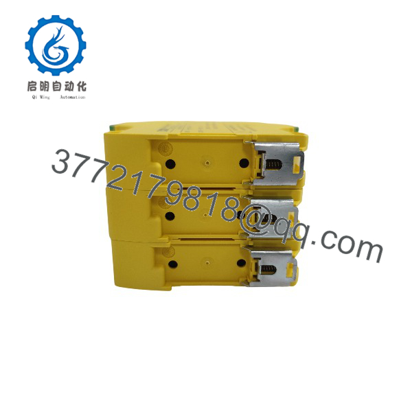
PSR-SPP- 24UC/URM4/5X1/2X2/B
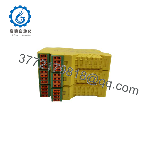
PSR-SPP- 24UC/URM4/5X1/2X2/B
System Compatibility & Integration Requirements
| Item / Dependency | Verified Compatibility or Requirement | Practical Note |
|---|---|---|
| System role | Contact extension module of the PSRclassic modular safety relay system | Must be operated together with a basic safety device (evaluating device); it does not monitor sensors itself. |
| Safety level | Up to Cat. 4, PL e (EN ISO 13849); SIL 3 (IEC 61508, EN IEC 62061) | Rating applies only in conjunction with a suitable evaluating device. |
| Control supply | 24 V AC/DC, −15 % / +10 % | Shares the control voltage level typical of the PSRclassic basic devices. |
| Control scheme | 1- or 2-channel | The extension can follow a single- or two-channel safety architecture, matching the basic device’s channel structure. |
| Feedback monitoring | Force-guided contacts per IEC/EN 61810-3; N/C signaling path | Supports the external contact-fault detection expected in higher-category circuits. |
| Installation environment | IP20 housing; installation location min. IP54; max. 2000 m altitude; −20…55 °C with derating | Intended for industrial control cabinets, per the “only for industrial use” application note. |
| Mounting | DIN rail, vertical or horizontal | 22.5 mm width; observe derating curve for assembly. |
| Wiring | Push-in, 0.2–1.5 mm² rigid or flexible (0.25–1.5 mm² with ferrule), 24–16 AWG, 8 mm strip length | Pluggable terminal blocks; use a CRIMPFOX 6 tool for ferruled flexible conductors. |
| Output protection | 10 A gL/gG fuse for enabling paths; 6 A gL/gG for signaling/confirmation paths | Required external fusing per the output data. |
Dimensions, Mounting & Connection Notes
The module measures 22.5 mm wide, 112 mm high, and 114.5 mm deep, and mounts on a DIN rail in either vertical or horizontal orientation. Electrical connection is via pluggable Push-in terminal blocks accepting rigid or flexible conductors of 0.2–1.5 mm² (24–16 AWG); flexible conductors with ferrules are supported at 0.25–1.5 mm², and the stripping length is 8 mm. A single green LED indicates the operating voltage. The enclosure is IP20, so the installation location must provide at least IP54; the operating temperature range is −20 °C to +55 °C with derating, and the maximum installation altitude is 2000 m.
Detailed Product Overview
Safety functions in machinery frequently need to interrupt more actuator circuits than a basic safety relay has outputs. A press or machining cell may have several motor contactors, braking circuits, and supply buses that must all open when the emergency stop is pressed — and all of them through contacts that are themselves part of the verified safety chain. Phoenix Contact’s PSRclassic system answers this with a two-part architecture: a basic device that evaluates the safety sensors, and extension modules like the PSR-SPP- 24UC/URM4/5X1/2X2/B that multiply the number of safe outputs under the basic device’s control.
This particular extension carries the highest output count of its 22.5 mm class: five enabling current paths, plus a signaling current path and a confirmation current path. All power contacts are AgSnO₂ and the relay element uses force-guided contacts built to IEC/EN 61810-3 — the mechanical construction that guarantees a defined relationship between N/O and N/C contacts, so a welded N/O contact keeps the N/C path open and is detected by the circuit’s monitoring logic. This property is what allows the module to be used in Category 4 / PL e architectures, but the datasheet is careful with the wording: the module reaches Cat. 4 / PL e and SIL 3 only “in conjunction with a suitable evaluating device.” The extension inherits the safety level of the safety function as a whole; buying a SIL 3-rated extension does not make a lower-level basic circuit SIL 3.
Electrically, each enabling path switches 5–250 V AC/DC at up to 6 A continuous, with inrush tolerance of 20 A for 100 ms — enough for contactor coil inrush — and standardized ratings of 2.5 A at 24 V DC13 and 3 A at 230 V AC15 per IEC 60947-5-1. The limiting continuous current and the squared total current (ΣI² = 72 A²) are subject to the derating curve, so dense multi-actuator loads at elevated ambient temperature must be checked against that curve rather than against the headline 6 A figure. External fusing is specified (10 A gL/gG for the enabling paths), and the maximum switching frequency is 1 Hz, consistent with safety switching duty rather than process-duty cycling.
The control side is deliberately simple: 24 V AC/DC with a −15 %/+10 % window, a varistor for surge suppression, and a 2 ms filter for dips at the supply. There is no configuration software or parameterization — the module’s behavior is determined by how the basic device drives it and by the 1- or 2-channel wiring chosen at installation. That makes replacement straightforward: a failed module is exchanged like-for-like on the DIN rail, and because the terminal blocks are pluggable, pre-wired blocks can be transferred to the new unit.
Applications & System Role
In a machine safety circuit, the PSR-SPP- 24UC/URM4/5X1/2X2/B sits downstream of a PSRclassic basic safety relay. When the basic device evaluates a safety command — an emergency stop, a safety door, or a two-hand control — and drops out its own outputs, the extension module’s five enabling current paths open the additional actuator circuits that the basic device cannot cover alone: additional motor contactors, field-shutoff valve drivers, or multiple machine sections that must all de-energize on the same safety function. The signaling current path reports the module’s contact state, and the confirmation current path feeds the reset/feedback loop of the safety circuit. The module implements stop category 0 per EN 60204-1. It is an industrial-use component specified for installation in control cabinets meeting the stated environmental conditions.
FAQ
What is the Phoenix Contact PSR-SPP- 24UC/URM4/5X1/2X2/B?
It is a safety relay extension module from the PSRclassic family that adds safe output contacts to a basic safety device, providing 5 enabling current paths, 1 signaling current path, and 1 confirmation current path.
What is its order number?
Phoenix Contact order number 2981046.
Can it be used alone as an emergency-stop relay?
No — it is a contact extension with no sensor evaluation function of its own; it must be operated together with a suitable basic (evaluating) safety device.
What safety level does it achieve?
Up to Category 4 / Performance Level e per EN ISO 13849 and SIL 3 per IEC 61508 and EN IEC 62061, in each case only in conjunction with a suitable evaluating device.
What supply voltage does it need?
24 V AC/DC with a tolerance of −15 % / +10 %; typical current consumption is 71 mA (DC) or 81 mA (AC).
How much current can the outputs switch?
Each path switches 5–250 V AC/DC at up to 6 A continuous (with derating), 2.5 A at 24 V DC13 and 3 A at 230 V AC15 per IEC 60947-5-1, with inrush capability of 20 A for 100 ms.
How is it wired and mounted?
Pluggable Push-in terminals for 0.2–1.5 mm² (24–16 AWG) conductors with 8 mm stripping length; DIN rail mounting, vertical or horizontal, in a housing 22.5 mm wide.
What environmental limits apply?
IP20 housing requiring an installation location of at least IP54, operating temperature −20 °C to +55 °C with derating, storage −40 °C to +70 °C, maximum altitude 2000 m, and vibration of 10–150 Hz at 2g.