
 WhatsApp: +86 16626708626
 Email:
  Phone: +86 16626708626
Description
Key Technical Specifications
| Parameter | Value |
|---|---|
| Model Number | 301130 |
| Manufacturer | Pilz |
| Product Designation | PSS SB DI16 |
| Product Series | PSS 3000 SafetyBUS p |
| Product Type | Safety digital input module |
| Field Input Count | 16 digital inputs |
| Test-Pulse Output Count | 4 test-pulse outputs |
| Nominal Supply Voltage | 24 V DC |
| Communication System | SafetyBUS p |
| Installation Method | Modular PSS safety-system I/O station |
| Protection Rating | IP20 |
| Typical Input Devices | Emergency-stop contacts, safety gates, light curtains, interlock switches, two-hand controls, pressure mats, and safe-position contacts |
| Diagnostic Role | Reports input and module status to the PSS/SafetyBUS p safety controller |
| Safety Function Role | Input acquisition only; final safety behavior depends on controller programming, system architecture, wiring, and validation |
| Replacement Requirement | Match module type, SafetyBUS p station position, input wiring, test-pulse assignment, and validated safety project |
| Lifecycle Status | Legacy PSS 3000 / SafetyBUS p hardware; confirm stock and migration support before planning a shutdown |
Public supplier listings identify the Pilz 301130 PSS SB DI16 as a 24 V DC SafetyBUS p digital input module with 16 inputs, four test-pulse outputs, and IP20 protection. Exact electrical limits, safety category, performance level, SIL rating, terminal assignment, and firmware compatibility must be verified from Pilz OEM documentation for the installed system version.
Product Introduction
The Pilz 301130 PSS SB DI16 is a 16-channel safety digital input module for Pilz PSS 3000 SafetyBUS p installations. It collects 24 V DC field signals from safety devices such as emergency-stop stations, guard-door switches, light curtains, safety mats, and position contacts, then transmits their status through the safety I/O system.
This module does not create a safety function by itself. The PSS safety controller, validated application program, safety-device wiring, test-pulse assignment, and final output circuitry determine the machine’s actual safe state. When replacing a 301130, preserve the station address, physical slot, terminal wiring, test-pulse configuration, and validated project file.
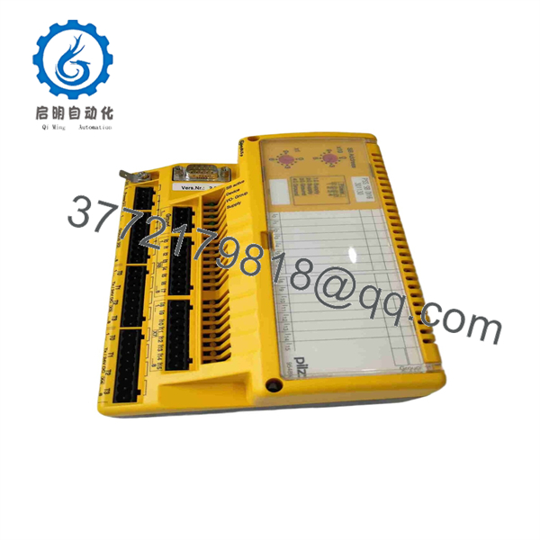
301130
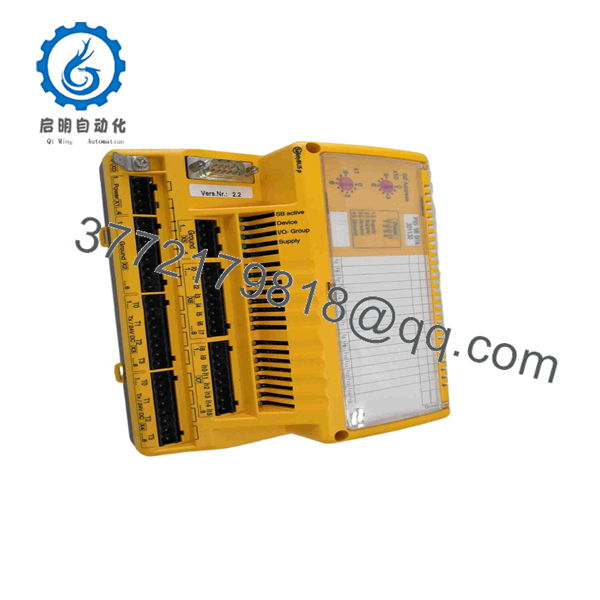
301130
Troubleshooting Quick Reference
| Symptom | Possible Cause | Relevance to This Part | Quick Check Method | Recommendation |
|---|---|---|---|---|
| Module has no status indication | Missing 24 V DC supply, blown fuse, loose station connection, failed power distribution, module fault | ✅ High | Measure 24 V DC and 0 V at the station power terminals with a calibrated multimeter. Check upstream fuses, power supply LEDs, and adjacent PSS module status. | Restore stable supply power before replacing the 301130. A failed common power feed can make several I/O modules appear defective. |
| One safety input remains OFF with device closed | Open field conductor, loose terminal, failed guard switch contact, missing test pulse, incorrect wiring, input-channel fault | ✅ Medium | Isolate the machine under the approved lockout procedure. Measure the input voltage at the module terminal while operating the field device. Compare with a known-good input. | Diagnose the field device and cable first. Replace the module only if valid input voltage reaches the terminal but the channel remains inactive. |
| Safety controller reports a test-pulse fault | Test-pulse output shorted, cross-circuit between channels, wrong wiring, incorrect sensor type, water ingress | ✅ High | Identify the affected test-pulse group in the Pilz diagnostic software. Disconnect field cables one at a time under controlled conditions and inspect for shorts to 0 V, +24 V, or adjacent inputs. | Repair the cable or device fault. Do not bypass test-pulse diagnostics; they are intended to detect cross-faults in safety circuits. |
| Emergency stop does not reset after release | E-stop contact block damaged, dual-channel mismatch, reset logic not satisfied, feedback loop fault, input wiring error | ❌ Low | Check both E-stop contact channels at the 301130 terminals. Review the safety-controller diagnostic state and reset permissive conditions. | Repair the device or logic condition. The input module only reports the signals it receives. |
| Safety gate shows open when physically closed | Misaligned actuator, failed tongue/RFID switch, broken cable, incorrect input channel, test-pulse issue | ✅ Medium | Inspect mechanical alignment, measure both contact channels at the module, and confirm the configured channel mapping in the safety project. | Correct actuator alignment or cable faults before replacing the module. |
| Multiple inputs fail after replacement | Wrong module type, module installed in the wrong position, station addressing issue, terminal wiring moved, project mismatch | ✅ High | Compare the replacement label to the old PSS SB DI16. Verify station topology, physical order, terminal numbers, and project diagnostics before energizing. | Install only the matching 301130 module and restore original placement and wiring. Revalidate the safety function after replacement. |
| Input status flickers during machine vibration | Loose terminal, damaged conductor, failing mechanical switch, poor cabinet ground, intermittent connector contact | ✅ Medium | Trend the input in Pilz diagnostics while gently checking cables and terminals with power isolated where required. Inspect for vibration damage and conductor fatigue. | Re-terminate or replace damaged field wiring. Do not use input filtering to hide an intermittent safety circuit. |
| Module reports bus communication fault | SafetyBUS p cable issue, station connector not seated, controller fault, bus topology problem, duplicate address | ✅ Medium | Inspect SafetyBUS p connectors and module seating. Review controller diagnostics and confirm neighboring modules communicate correctly. | Correct the bus and station issue before replacing the I/O module. |
| Machine remains stopped after a good input state appears | Safety controller program, reset circuit, contactor feedback loop, output module, external safety relay, field actuator condition | ❌ Low | Confirm the 301130 input LED and diagnostic state, then trace the safety logic through the PSS controller, output module, feedback contacts, and final elements. | Do not replace a healthy input module for an output-side or program-side safety fault. |
| Module or terminals show heat, corrosion, or moisture | Loose conductor, cabinet ingress, power transient, contaminated environment, incorrect wire size | ✅ High | Lock out and inspect terminals, module connector, panel seals, cable glands, and conductor condition. Measure for voltage drop under load where applicable. | Replace damaged hardware and correct the source of heat or moisture before commissioning the replacement. |
❗ Do not treat a safety input like a standard PLC input. The 301130 participates in a validated safety function. Any forced input, jumper, bypass, wiring change, or test-pulse modification must follow the machine’s approved safety procedure and risk assessment.
❗ Photograph all terminals before removal. A PSS SB DI16 can have 16 field inputs and four test-pulse outputs. Swapping a test-pulse conductor with a standard 24 V supply can create a fault that looks like a failed module but is really a wiring mistake.
❗ Record the safety project and station topology. The module must return to the same SafetyBUS p architecture, physical position, and validated PSS configuration. I have seen a replacement module installed one position over, after which the safety controller correctly reported an I/O mismatch and the machine could not reset.
❗ Never use a jumper to “prove” a safety input without authorization. You can defeat cross-fault detection, bypass a guard circuit, or create an unsafe reset condition. Use approved test equipment and the site’s controlled validation process.
If you are stuck, provide technical support with photos of the 301130 label, station order, SafetyBUS p connectors, terminal wiring, module LEDs, diagnostic screenshots, input-voltage measurements, and the safety-project version. Keep these checks in mind and you will save yourself 90% of typical rework time.
Frequently Asked Questions (FAQ)
What is the Pilz 301130 PSS SB DI16 used for?
The Pilz 301130, designated , is a SafetyBUS p safety digital input module. It accepts up to 16 digital field-input signals and provides four test-pulse outputs for monitored safety-device circuits in a Pilz PSS safety automation system.
How many inputs does the 301130 have?
It has 16 digital inputs and four test-pulse outputs. The module uses a 24 V DC supply and communicates over SafetyBUS p.
Can I use this module as a normal remote I/O input card?
It can read 24 V DC signals, but it is designed for the Pilz PSS 3000 SafetyBUS p safety-I/O architecture. Use it only in a compatible PSS system with the correct controller, bus topology, project configuration, and safety validation. It is not a drop-in replacement for a standard PLC digital-input card.
Is the 301130 a standalone safety relay?
No. It is a modular safety input module. It needs a compatible PSS safety controller and SafetyBUS p I/O station. The controller program and associated output modules determine whether a guard door, emergency stop, light curtain, or other device causes a safe stop.
Can I hot-swap the Pilz 301130?
Do not assume hot swapping is allowed. Removing a safety I/O module can trigger a system fault, place the machine into a safe state, or prevent restart until the station is recognized and validated. Follow the plant’s lockout, change-control, and machine safety procedures before servicing it.
Why does the module show an input fault even though the field switch appears closed?
Common causes are a broken second channel, a missing or shorted test pulse, cross-wiring, a loose terminal, a failed contact block, a wrong switch type, or incorrect input mapping in the safety project. Check both channels and the test-pulse circuit at the module terminal. A single continuity check at the switch is not enough.
Will replacing the 301130 erase the safety program?
The safety project resides in the controller or engineering environment, not normally in the input module. However, the replacement can still create an I/O mismatch or failed safety validation if the module type, station position, wiring, test-pulse assignment, or project version differs from the original. Back up the project and document the station before removal.
Is the Pilz 301130 obsolete, and should I keep a spare?
Treat the PSS 3000 SafetyBUS p platform as legacy hardware and confirm current lifecycle status with Pilz for your region. For a production machine that depends on this module, retain an exact matching spare and preserve the safety project, wiring drawings, I/O list, validation report, and commissioning checklist. If replacement availability is limited, plan a controlled migration rather than waiting for a shutdown.



