WhatsApp: +86 16626708626
 Email:
 Phone: +86 16626708626
Description
Key Technical Specifications
The table separates supported identification from unverified technical claims. It is not an installation datasheet.
| Parameter | Value |
|---|---|
| Full Model | PCU10.24-48D |
| Manufacturer Identification | POWEC in exact-model listings; verify the physical label |
| Product Category | Power-system control and display unit |
| Primary Function | Monitoring and control of a rectifier-based DC power system |
| Operator Interface | Integrated display and local controls; exact display specification requires confirmation |
| Operating Supply | Unverified; do not infer from the model number |
| Supported System Voltage | References associate the unit with 24/48 V DC power systems; controller supply and sensing limits require separate verification |
| Rectifier Compatibility | Secondary references identify PMP10.00SIC and PMP11.48SIC; confirm against the actual rack and firmware |
| Communication | RS-232 reported in secondary technical descriptions; connector pinout and settings unverified |
| Alarm Interfaces | External alarm contacts reported; quantity, contact type, ratings, and fail-state unverified |
| Firmware and Configuration | Installed revision, parameter retention method, and backup procedure unverified |
| Mechanical and Environmental Ratings | Dimensions, weight, connector assignments, and operating temperature unverified |
Identification and reported functions come from exact-model listings and secondary technical descriptions. A Power-One PCU10 datasheet index supports the family’s controller classification, but does not establish the complete PCU10.24-48D specification.
Do not publish “48 V / 10 A,” “480 W,” “220 V AC input,” or “24-to-48 V converter” as established specifications. Conflicting reseller pages make those claims without a verified, matching OEM document.
Product Introduction
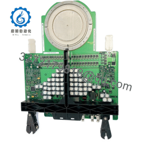
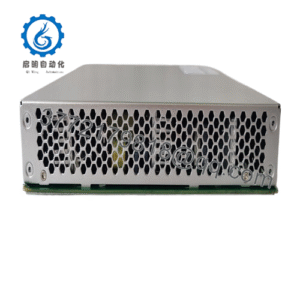
The POWEC PCU10.24-48D is identified in available references as a power-system control and display unit for supervising rectifier-based DC installations. Its role centers on operating information, system settings, and alarms—not a verified standalone power-conversion output.
For replacement procurement, match the complete nameplate, rack interface, rectifier family, firmware, and stored parameters. The model number alone does not establish supply voltage, connector compatibility, or a safe installation procedure.
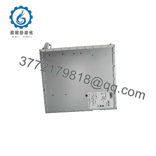
PCU10.24-48D
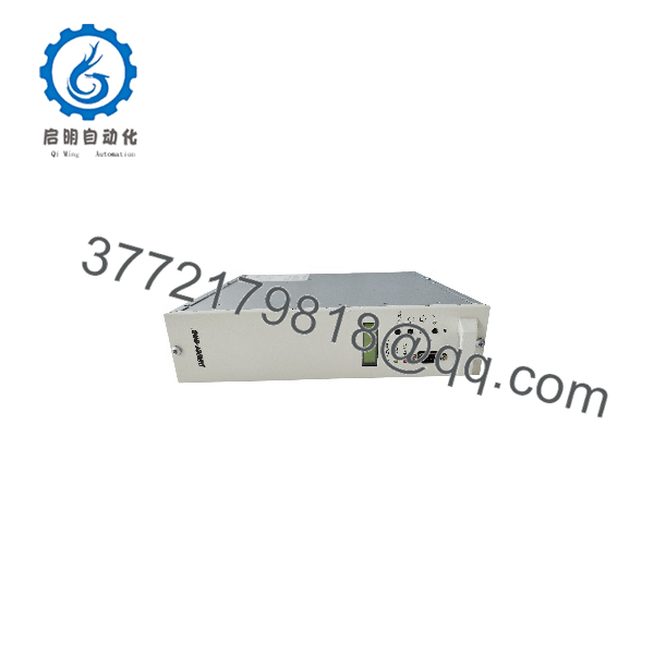
PCU10.24-48D
Troubleshooting Quick Reference
| Symptom | Possible Cause | Relevance to this Part | Quick Check Method | Recommendation |
|---|---|---|---|---|
| Display completely dark | Missing controller supply, rack fuse, poor connection, or internal fault | External supply checks first | Identify the controller supply pins from the rack drawing; measure voltage and polarity at those documented points | Do not energize an unidentified connector or assume a supply rating |
| Display operates but readings appear incorrect | Wrong parameters, sensing wiring fault, or calibration issue | Controller or sensing circuit possible | Compare displayed DC voltage with a suitable calibrated meter at the documented bus measurement points | Verify sensing wiring and configuration before replacement |
| One rectifier reports a fault | Rectifier failure, missing input, module communication, or controller configuration | Controller is not automatically the cause | Compare the affected rectifier’s indicators and local measurements with the controller message | Diagnose the individual module and its supply first |
| All rectifiers disappear from the display | Shared communication fault, rack-interface issue, or controller failure | Controller path requires isolation | Inspect documented interconnects with power isolated; compare the installed module list and configuration with records | Check shared wiring before replacing multiple components |
| Alarm output disagrees with displayed status | Relay configuration, external wiring, or contact fault | Alarm interface requires testing | Identify the correct contacts and ratings from the wiring diagram; test the isolated alarm circuit under an approved procedure | Never inject test voltage into unidentified alarm pins |
| Remote monitoring stops but local display works | Cable, serial settings, host software, or interface fault | Communication path first | Verify the actual interface, cable pinout, host settings, and error records against the working configuration | Do not assume Ethernet, Modbus, or a standard serial pinout |
| Settings differ after replacement | Wrong firmware, missing configuration, or incompatible unit variant | Replacement compatibility directly relevant | Compare old/new labels, firmware displays, parameter records, and rack application | Restore only a verified compatible configuration |
| System raises alarms but DC output remains present | Genuine external fault or controller alarm logic | Alarm does not prove controller failure | Record the exact alarm and independently verify the associated voltage, fuse, rectifier, or battery condition | Diagnose the alarm’s source before ordering a controller |
These are conservative diagnostic checks based on the reported control/display role—not OEM fault-code interpretations. Exact LED meanings, terminal numbers, and service procedures remain unverified.
If the issue remains, contact technical support with front/rear photos, the complete nameplate, rack and rectifier models, exact alarm text, firmware information, wiring drawings, and measured values.
Frequently Asked Questions (FAQ)
Is the PCU10.24-48D a controller or a 24-to-48 V power converter?
The better-supported identification is a power-system controller/display unit. An exact-model marketplace listing calls it a “Control Unit Display,” another exact-model source describes microprocessor-based power-system control, and the PCU10 family datasheet index classifies it as a controller module.
Converter claims conflict with that identification. Do not interpret “10” as 10 A, or “24-48” as a conversion ratio, without the matching OEM specification. Do not connect a load expecting regulated 48 V output on that basis.
Will any PCU10.24-48D replace my existing unit?
That has not been established. Match the full label, hardware revision, firmware, rack interface, connector assignments, supported rectifiers, and site configuration.
Secondary descriptions associate this unit with specific PMP rectifiers and power-rack functions, but those descriptions do not establish universal interchangeability.
For a purchase order, require the supplier to identify the actual unit—not merely quote the base model. Do not accept “equivalent” without a documented compatibility basis.
What firmware and configuration information should I save?
Before removal, record every accessible identification screen and parameter page. Where applicable to the installed system, capture:
- System voltage and voltage setpoints.
- Alarm thresholds and delays.
- Rectifier inventory and addressing.
- Battery-related settings.
- Alarm relay assignments and logic.
- Remote communication settings.
- Installed firmware and hardware identifiers.
The reported functions include parameter configuration, alarms, battery-related monitoring, and remote supervision, but the exact export method and supported software versions have not been verified.
Do not factory-reset a working controller or promise configuration retention without the applicable manual. Likewise, do not claim a specific firmware range is interchangeable.
Can I hot-swap it, and should I copy switches or jumpers?
Hot-swap capability is unverified. Do not infer it from the fact that other modules in the rack may be removable under power.
A controller change could affect supervisory functions or alarm behavior. Establish the approved maintenance procedure and safe system state before disconnecting it. Use grounded ESD protection when handling the electronics.
Photograph any actual switches, jumpers, connectors, and slot positions before removal. No verified switch map was found, so do not invent node-address, baud-rate, or termination settings. Copy settings only after confirming that the replacement uses the same hardware configuration.
What supply and wiring checks matter most?
Obtain the controller’s actual supply specification and the rack pinout first. Distinguish between:
- Voltage powering the controller.
- Voltage being measured.
- Rectifier output voltage.
- Battery-system voltage.
- Alarm-contact ratings.
These values are not automatically identical. Secondary sources report an 18–72 V DC range, but a matching OEM specification was not verified; do not use that figure alone to authorize energization.
Check polarity, grounding, fuse requirements, connector keying, and wire assignments against the site drawing. For supply planning, a 20% capacity allowance can provide margin after the real load is known. It does not establish the missing controller rating or override OEM limits.
Is it obsolete, available as new surplus, or covered by a warranty?
Current OEM lifecycle classification, actual stock, condition, dispatch date, and warranty are unverified. Resale listings establish that units have been offered—not current availability or fitness for your application.
Require a written quote stating:
- Complete model, serial number, and revision.
- Actual quantity and committed dispatch date.
- New Original / New Surplus, Factory Sealed, used, or Refurbished (tested), supported by records.
- Repair history and configuration status.
- Included accessories and connectors.
- Test-report scope.
- Warranty duration, exclusions, and return terms.
A lower price alone proves neither authenticity nor condition. Do not claim OEM warranty, recent manufacture, or factory sealing without evidence.
What inspection and testing should the supplier document?
Request the following serial-linked acceptance process. No actual-unit inspection or testing records were supplied.
- Inbound inspection and traceability
Review available OEM packing lists, purchase records, and applicable customs declarations. Cross-check labels and serial numbers. Inspect for corrosion, scratches, rework, discoloration, connector damage, and evidence of leakage from any fitted retention component. Audit accessories and certificates. Check security markings only where the production version actually used them. - Live functional testing
Identify the compatible POWEC rack, rectifier modules, safe DC supply, documented wiring, and calibrated instruments. Record the boot sequence, display condition, local controls, reported module inventory, and measurement agreement. Exercise documented alarms and communication functions using an approved simulation method. For a required run exceeding 24 hours, record duration, configuration, temperatures, alarms, and errors. Do not fabricate a test-rack model or instrument brand. - Electrical parameter testing
Use the applicable service procedure for supply-current, measurement, grounding, and alarm-contact checks. Do not apply a blanket 500 V megohmmeter or hipot test to controller electronics, communication ports, or sensing inputs. Require an OEM-approved method and defined test points before high-voltage testing. - Firmware and configuration verification
Record accessible firmware/hardware identifiers. Preserve the parameter set, actual switch/jumper photographs, and connector mapping. Document what was backed up, what was changed, and which settings remain site-specific. - Final QC and packaging
Require inspector sign-off, a dated serial-linked report, ESD shielding packaging, display and connector protection, cushioning, a rigid corrugated box, and a dated QC label. Request actual-unit test photos and videos where available. Publish a functional-test claim only when the report identifies the tested conditions and results.