WhatsApp: +86 16626708626
 Email:
 Phone: +86 16626708626
Description
Key Technical Specifications
| Parameter | Specification |
|---|---|
| Manufacturer | ProSoft Technology |
| Model | MVI56-PDPS |
| Module type | PROFIBUS DP Slave Communication Module |
| Host platform | Rockwell Automation ControlLogix |
| Backplane compatibility | Single-slot 1756 chassis |
| PROFIBUS role | Slave |
| Protocol | PROFIBUS DP V0 |
| PROFIBUS master | External PROFIBUS DP master required |
| Input data | Up to 244 bytes |
| Output data | Up to 244 bytes |
| Total I/O data | Configuration-dependent; consult the applicable manual for the aggregate limit |
| Data mapping | User-configurable mapping between PROFIBUS data and module memory |
| Processor data transfer | ControlLogix I/O image and ladder logic |
| Configuration method | Configuration text file downloaded to the module |
| Configuration software | ProSoft Configuration Builder |
| Diagnostic interface | Serial configuration/debug port |
| GSD file | Available from ProSoft for PROFIBUS master configuration |
| Backplane current draw | 800 mA at 5 VDC; 3 mA at 24 VDC |
| Operating temperature | 0°C to 60°C (32°F to 140°F) |
| Storage temperature | −40°C to 85°C (−40°F to 185°F) |
| Relative humidity | 5–95%, non-condensing |
| Shock resistance | 30 g operational; 50 g non-operational |
| Vibration resistance | 5 g from 10–150 Hz |
| Mounting | Local or remote ControlLogix rack, subject to system configuration |
Source: ProSoft Technology’s MVI56-PDPS datasheet and user manual. The product documentation describes a PROFIBUS DP V0 slave implementation. Confirm the supported data size and configuration limits in the manual revision applicable to the installed module.
Product Introduction
The ProSoft MVI56-PDPS is a PROFIBUS DP slave communication module for Rockwell Automation ControlLogix systems. It allows a ControlLogix processor to exchange process data with a PROFIBUS DP master, such as a PLC or distributed control system. The module implements PROFIBUS DP V0 slave functionality and provides user-configurable mapping of network input and output data into its internal data memory. Ladder logic transfers that information between the module and the ControlLogix processor.
The module is suited to installations where a ControlLogix controller must participate in an existing PROFIBUS network without replacing the network master. Typical applications include process control, power distribution, water and gas systems, and SCADA or DCS integration. Because the MVI56-PDPS is a legacy product, replacement planning should include verification of the GSD file, PROFIBUS configuration, data mapping, controller logic, and network timing. ProSoft identifies the ILX56-PBS as a replacement option, but compatibility should be validated before migration.
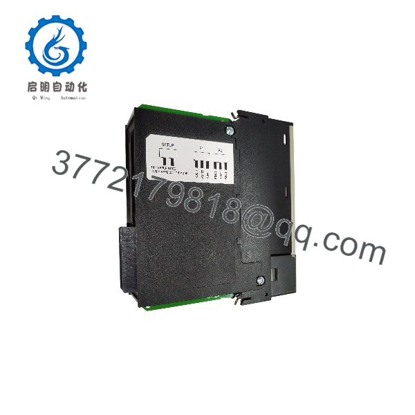
MVI56-PDPS
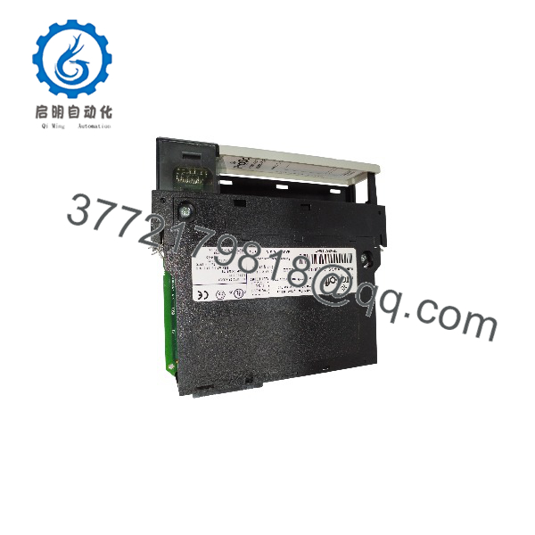
MVI56-PDPS
Installation & Configuration Guide
Estimated times are planning estimates, not manufacturer-specified installation durations.
Stage 1 — Verify compatibility and back up the project
Estimated time: 15–30 minutes
- Confirm the complete model number is MVI56-PDPS.
- Verify the ControlLogix chassis and available slot.
- Back up the ControlLogix project, associated ladder logic, and ProSoft configuration file.
- Obtain the applicable MVI56-PDPS GSD file and record the existing PROFIBUS network settings.
- Document the configured input and output data sizes and mapping.
Stage 2 — Install the module and prepare the network
Estimated time: 15–30 minutes
- Place the system in a safe state and follow site lockout/tagout procedures.
- Install the module according to the ControlLogix hardware instructions.
- Connect the PROFIBUS cable and configuration/debug interface as shown in the applicable manual.
- Check bus wiring, connector orientation, shielding, termination, and grounding.
- Confirm the network master is configured to recognize the slave.
Stage 3 — Configure the PROFIBUS slave and PLC data mapping
Estimated time: 30–90 minutes
- Use ProSoft Configuration Builder to prepare the module configuration.
- Configure the required PROFIBUS operating parameters and data sizes.
- Import the correct GSD file into the PROFIBUS master engineering software.
- Configure the slave in the master project using the required input and output lengths.
- Configure the ControlLogix ladder logic to transfer data between the processor and module.
- Check the data offsets and confirm that both ends use matching layouts.
Stage 4 — Commission and validate communication
Estimated time: 30–60 minutes
- Check module status indicators and diagnostic information.
- Verify that the PROFIBUS master recognizes the slave and establishes cyclic data exchange.
- Test representative input and output values.
- Confirm the mapped data appears in the intended ControlLogix tags.
- Check for bus faults, configuration mismatches, and stale data.
- Save the validated configuration and update the network documentation before returning the system to normal service.
Commissioning caution: The GSD configuration, data lengths, and ControlLogix mapping must agree. A slave can be physically connected to the bus yet fail to exchange cyclic data if the master configuration or data lengths are incorrect.
Frequently Asked Questions
Q1: What is the ProSoft MVI56-PDPS used for?
It connects a ControlLogix processor to a PROFIBUS DP master as a slave device, allowing process data to be exchanged between the PROFIBUS network and the ControlLogix application.
Q2: Does the MVI56-PDPS support PROFIBUS DP V1?
The documented protocol implementation is PROFIBUS DP V0 slave. Do not assume DP V1 acyclic messaging is supported by this module. If DP V1 functionality is required, evaluate a suitable alternative and verify its feature set.
Q3: What is the maximum input and output data size?
ProSoft’s product documentation specifies up to 244 bytes of input data and up to 244 bytes of output data. The applicable manual should be consulted for the total configured data limit and any restrictions on the combined I/O image.
Q4: Does the MVI56-PDPS require a PROFIBUS master?
Yes. The module operates as a slave, so a compatible PROFIBUS DP master is required to initiate and manage network data exchange. The master engineering project must include the correct GSD file and slave configuration.
Q5: How is the module configured?
The module uses a configuration text file prepared with ProSoft Configuration Builder. A GSD file is provided for configuring the module in the PROFIBUS master project, and ladder logic is used for data transfer between the module and the ControlLogix processor.
Q6: Is the MVI56-PDPS still a current product?
ProSoft lists it under its legacy products. Its official product page provides the datasheet, user manual, configuration file, GSD file, sample ladder logic, and a lifecycle letter. Confirm present availability, support, and repair options directly with ProSoft or a qualified supplier.
Q7: What should be checked before ordering a replacement?
Verify the full model number, hardware condition, required PROFIBUS data sizes, GSD configuration, ControlLogix logic, and existing master settings. ProSoft identifies the ILX56-PBS as a replacement option for the MVI56-PDPS. However, the replacement may require ladder-logic changes, so confirm the migration requirements before ordering.