
 WhatsApp: +86 16626708626
 Email:
  Phone: +86 16626708626
Description
3. Key Technical Specifications
| Parameter | Value |
|---|---|
| Part Number | 9440/15-01-11 (Art. No. approx. 203584) |
| Manufacturer | R. STAHL |
| Series | IS1 / IS1+ Remote I/O |
| Function | CPU + intrinsically safe power supply |
| Fieldbus Protocol | Profibus DP V0 / V1 (HART capable) |
| Redundancy Support | System redundancy + optical ring |
| Max. I/O Modules | Up to 16 IS1+ modules |
| Bus Connection | RS-485, 9-pin Sub-D |
| Service Bus | RS-485, 9-pin Sub-D |
| Installation | Zone 2 / Division 2 |
| Temperature Class | T4 (Ta = 65 °C) |
| Approvals | ATEX, IECEx, FM, NEPSI, KTL, marine (ABS, DNV, LR, etc.) |
| Power Supply | Intrinsic-safe supply for connected I/O |
4. Product Introduction
The R. STAHL 9440/15-01-11 is the CPU and power supply module for the IS1 / IS1+ remote I/O system designed for Zone 2 / Division 2 hazardous areas. It supplies intrinsically safe power to up to 16 I/O modules and handles communication with the higher-level automation system via Profibus DP (V0/V1, including HART).
This module is used when engineers need a compact, certified remote station in hazardous locations for process signals without running long intrinsically safe cable runs back to the control room. It supports system redundancy and optical ring topologies. The 9440/15-01-11 is the central component that makes the entire IS1+ station operational.
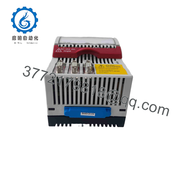
9440/15-01-11
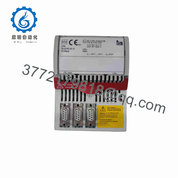
9440/15-01-11
5. Troubleshooting Quick Reference
| Symptom | Possible Cause | Relevance to this Part | Quick Check Method | Recommendation |
|---|---|---|---|---|
| No communication on Profibus | Wrong address, bus termination, or cable fault | ✅ High | Verify station address, check termination resistors, measure bus voltage | Correct address and termination; inspect Sub-D connectors |
| I/O modules not powered | Power supply failure or overload | ✅ High | Measure IS power output; check total load of connected modules | Reduce module count or replace CPM if output is missing |
| Module not recognized | Firmware / configuration mismatch | ✅ Medium | Check ServiceBus connection and DTM configuration | Update configuration via FDT/DTM tools |
| Redundancy switchover fails | Optical ring or redundancy wiring error | ✅ High | Verify optical ring integrity and redundancy settings | Inspect fiber/copper ring and redundancy parameters |
| Temperature or fault LED active | Over-temperature or internal fault | ✅ High | Check ambient temperature and ventilation | Improve cooling; replace module if fault persists |
| HART devices not visible | HART not enabled or incorrect mapping | ✅ Medium | Confirm HART configuration in host system | Enable HART and map devices correctly |
If the station remains offline after these checks, record the LED status, Profibus address, connected module list, and clear photos of the wiring before contacting support.
6. Frequently Asked Questions (FAQ)
Q: Is the 9440/15-01-11 suitable for Zone 1?
No. It is certified for Zone 2 / Division 2 only. For Zone 1 applications a different IS1 version is required.
Q: How many I/O modules can one 9440/15-01-11 support?
Up to 16 IS1+ I/O modules, provided the total power budget is not exceeded.
Q: Does it support Profibus DP with HART?
Yes. It supports Profibus DP V0/V1 including HART passthrough for smart field devices.
Q: Can the module be used in a redundant configuration?
Yes. It supports full system redundancy and optical ring topologies according to PNO guidelines.
Q: What tools are needed for configuration?
A ServiceBus connection plus an FDT/DTM frame (or compatible asset management system) is used for configuration and diagnostics.
Q: Is this module still in production?
Availability should be confirmed with R. STAHL or authorized distributors. Many units on the secondary market are new surplus or carefully tested stock.
Q: What should I document before replacing a failed unit?
Photograph the current Profibus address setting, all connector wiring, LED states, and the exact list of connected I/O modules. This prevents most post-replacement configuration issues.



