
 WhatsApp: +86 16626708626
 Email:
  Phone: +86 16626708626
Description
Key Technical Specifications
| Parameter | Value |
|---|---|
| Model | 57C424 |
| Product type | MaxPak III High-Speed Link module |
| System | Reliance Electric AutoMax DCS |
| Drive interface | MaxPak III drive controller |
| Rack interface | AutoMax Multibus rack |
| Primary function | Direct communication link between AutoMax and MaxPak III drive controllers |
| 5 VDC backplane current | 2.40 A |
| +12 VDC backplane current | 0.053 A |
| −12 VDC backplane current | 0.008 A |
| +15 VDC current | 0 A |
| −15 VDC current | 0 A |
| Diagnostics | 7-segment fault-code display and green status LED |
| Drop-number setting | Set according to AutoMax/MaxPak III network configuration |
| Related manual | J2-3010, MaxPak III High-Speed Link Module Instruction Manual |
| Rack installation | AutoMax Multibus card rack; verify slot restrictions |
| Operating temperature | AutoMax catalog: 0 to 60 °C |
| Storage temperature | AutoMax catalog: −40 to 85 °C |
| Humidity | 5–90%, non-condensing |
| Lifecycle | Legacy/discontinued AutoMax hardware |
| Condition | Supplier-specific; listings include new sealed and used units |
The 57C424 is documented as the AutoMax MaxPak III High-Speed Link module and is designed for installation in an AutoMax DCS rack. The AutoMax catalog lists its backplane requirements as 2.40 A at 5 VDC, 0.053 A at +12 VDC, and 0.008 A at −12 VDC. The module includes a 7-segment fault-code display and green status LED, and its instruction manual is identified as J2-3010.
Product Introduction
The Reliance Electric 57C424 is an AutoMax MaxPak III High-Speed Link module used to connect an AutoMax DCS rack directly to MaxPak III drive controllers. It occupies an AutoMax Multibus rack position and exchanges drive-control data with the AutoMax processor system.
The module provides local diagnostic indication through a 7-segment fault display and green status LED. Because AutoMax and MaxPak III are legacy platforms, verify rack type, drop-number configuration, firmware or run-base version, drive interface wiring, and replacement test results before installation.
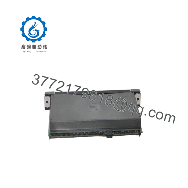
57C424
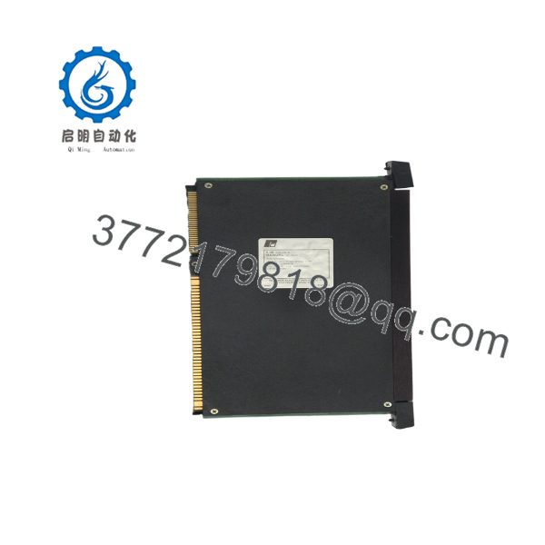
57C424
Troubleshooting Quick Reference
| Symptom | Possible Cause | Relevance to This Part | Quick Check Method | Recommendation |
|---|---|---|---|---|
| 57C424 has no display or status LED | Rack power failure, missing backplane voltage, poor seating, or module fault | ✅ Medium | Measure +5 VDC, +12 VDC, and −12 VDC at the rack test points or module connector per the manual | Check rack power and seating before replacing the module |
| All 7-segment indicators remain on | Firmware did not start, processor fault, or module initialization failure | ✅ High | Observe the display during boot and compare the indication with the 57C424 troubleshooting table | Replace or repair the module if the condition persists after verified rack power |
| AutoMax cannot communicate with MaxPak III | Incorrect drop number, cable fault, drive interface fault, or 57C424 failure | ✅ High | Verify the drop setting, inspect link wiring, and test communication with a known-good drive node | Correct configuration and wiring before replacing the card |
| One MaxPak III drive is missing | Drive-side fault, node/drop setting, cable termination, or module channel issue | ✅ Medium | Check the drive node address and cable continuity; compare with another active node | Isolate the fault to the drive or network branch before condemning 57C424 |
| Multiple drives disappear at once | 57C424 failure, shared cable, rack fault, or AutoMax network problem | ✅ High | Review AutoMax diagnostics and check whether all affected nodes share one link path | Inspect the common link and module before replacing individual drives |
| Communication is intermittent | Noise, loose connector, incorrect termination, vibration, or aging module | ✅ Medium | Monitor fault codes while inspecting connectors and measuring rack supply stability | Correct physical-layer problems first |
| Drop number is wrong after replacement | Switch or jumper setting not copied from original module | ✅ High | Photograph the original setting and compare every switch or jumper position | Mirror the original configuration before enabling drive control |
| Drive commands are present but response is incorrect | Mapping, scaling, run-base, or application configuration problem | ❌ Medium | Compare commanded and feedback values in AutoMax and MaxPak III diagnostics | Verify software configuration before replacing hardware |
| Module faults after installation in another slot | Slot restriction or rack configuration issue | ✅ High | Confirm the slot assignment against the AutoMax rack manual | Install only in a permitted rack position |
| Fuse or rack supply trips | Shorted module, connector misalignment, or rack power fault | ✅ High | Isolate power, inspect connectors, and compare resistance with a known-good card | Do not repeatedly reapply power; quarantine the module |
| 7-segment code appears after drive start | Drive-link protocol, node, or communication fault | ✅ High | Record the exact code and check the MaxPak III link status and drop configuration | Use the J2-3010 diagnostics and verify the drive-side connection |
| Module was handled without ESD protection | Damage to bus or communication circuitry | ✅ Medium | Perform controlled power-up and link testing after visual inspection | Use a grounded wrist strap and ESD-safe packaging |
Support note: If the fault remains, contact technical support with photos of the 57C424 label, 7-segment display, switch or jumper settings, rack slot, AutoMax diagnostics, MaxPak III drive model, cable layout, and measured backplane voltages.
Frequently Asked Questions
What is the Reliance 57C424?
It is the AutoMax MaxPak III High-Speed Link module. Its purpose is to provide a direct communication link between an AutoMax DCS rack and MaxPak III drive controllers.
Which rack does the 57C424 use?
The module is designed to reside in an AutoMax Multibus DCS rack. Confirm the rack model, available slot, backplane power capacity, and any slot-specific restrictions before installation.
What are the 57C424 power requirements?
The AutoMax catalog lists 2.40 A at 5 VDC, 0.053 A at +12 VDC, and 0.008 A at −12 VDC. Include those values in the rack power budget, especially when adding the module to an older or heavily loaded rack.
How is the drop number set?
The module uses a configured drop or node number for the MaxPak III link. The exact switch or jumper arrangement must be copied from the original module and verified against the AutoMax and MaxPak III network configuration. Never select a number by trial and error on a live drive network.
Can I hot-swap the 57C424?
Do not assume it is hot-swappable. Shut down and isolate the AutoMax rack and connected drive-control circuits before removing the card. A live removal can interrupt drive communication or damage the Multibus interface.
What does an all-on 7-segment display mean?
Rockwell Automation support information identifies an all-segment “8” condition as a case where the firmware never started, requiring module repair or replacement. Confirm rack voltages and seating first, then record the display state during boot.
Is the 57C424 obsolete?
It should be treated as legacy or discontinued hardware. Current stock appears through specialist suppliers and surplus channels, including new-sealed and used listings. Request the exact board photos, display test results, drop-setting verification, warranty, and return terms.
What should the supplier test before shipping?
Request a power-up test in a compatible AutoMax Multibus rack, 7-segment diagnostic verification, green status LED confirmation, drop-setting documentation, MaxPak III communication test, connector inspection, and a recorded backplane-current check. The supplier should identify the condition as New Original (New Surplus), Factory Sealed, or Refurbished (tested).



