
 WhatsApp: +86 16626708626
 Email:
  Phone: +86 16626708626
Description
Key Technical Specifications
- Manufacturer: Bosch Rexroth / Indramat
- Full Part Number: 109-0743-3B04-03
- Board Designation: NT19
- Product Classification: Power supply board / PC board / internal drive electronics subassembly
- Application: Compatible legacy Indramat servo-drive or motion-control equipment
- Assembly Scope: Board-level replacement; not a complete RAC servo amplifier, spindle drive, or standalone controller
- Related Part Numbers Seen in Listings: 109-0743-3A04-03 and 109-0743-3B04-04
- Revision Compatibility: Not publicly verified; do not substitute suffix variants without documented OEM approval
- Input Supply: Must be verified from the parent drive schematic; no reliable public board-level rating is available
- Output Rails: Must be verified from documented NT19 test points; no reliable public board-level output rating is available
- Firmware / Settings: Not publicly verified; record jumper settings, connector positions, and drive parameters before removal
- Physical Match Requirement: Confirm PCB layout, connectors, mounting points, component-side markings, and complete label before ordering
The exact part number is sold under both Indramat and Bosch Rexroth branding because Bosch Rexroth carries the Indramat legacy. Available sources consistently identify 109-0743-3B04-03 as an NT19 power-supply or PC-board assembly for legacy drive hardware, not a complete drive.
Product Introduction
The Bosch Rexroth Indramat 109-0743-3B04-03 is an NT19 internal power-supply and electronics-support board used in compatible legacy Indramat drive assemblies. It is intended for board-level service of an existing drive and should not be quoted as a complete servo amplifier, spindle drive, or motion-control unit.
Use this part when fault isolation identifies the NT19 board as the source of unstable control rails, no-start behavior, or an internal power-related failure. Verify the complete 109-0743-3B04-03 label, PCB layout, parent-drive type code, connector locations, and jumper configuration before ordering. Similar 109-0743 suffixes are not automatically interchangeable.
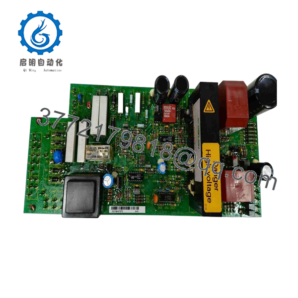
109-0743-3B04-03
Troubleshooting Quick Reference
| Symptom | Possible Cause | Relevance to This Part | Quick Check Method | Recommendation |
|---|---|---|---|---|
| Drive is dead with no display, LEDs, or control response | Missing incoming supply, blown fuse, control transformer failure, low-voltage supply failure, loose connector, or NT19 board fault | ✅ High | Apply lockout/tagout. Wait through the drive’s specified capacitor-discharge time. Verify DC-bus voltage is at a safe level with a correctly rated meter. Check line voltage, fuses, transformer secondary voltage, and documented low-voltage test points. | Verify incoming power and upstream protection before replacing the board. A failed board is not the only cause of a dead drive. |
| Drive starts but faults immediately | Enable-chain fault, unstable control rail, feedback problem, parameter issue, power-stage fault, or board malfunction | ✅ Medium | Record the full fault code before cycling power. Check the parent drive manual. Measure the documented control rails and inspect enable, inhibit, and feedback connections. | Diagnose the initiating fault. Do not replace the board only because the drive faults during startup. |
| Control voltage is low, unstable, or heavily rippled | Aged capacitors, regulator failure, overloaded secondary circuit, transformer issue, poor connector contact, or board defect | ✅ High | Measure the affected rail at the output and downstream load under safe operating conditions. Compare against the OEM schematic. Use isolated measurement equipment for ripple checks where authorized. | Isolate downstream loads if permitted. A shorted load can pull down a healthy supply rail. |
| Drive trips only when servo enable is applied | Shorted output transistor, motor cable fault, motor insulation failure, brake circuit issue, feedback fault, or control fault | ❌ Low to Medium | With power removed, inspect motor and feedback connectors. Perform approved motor insulation and phase-resistance tests. Review the fault history before replacing electronics. | Test the power stage, motor, and cable first. Do not use an board to chase a likely output-stage failure. |
| Fault occurs after 20–60 minutes of operation | Thermal stress, drying capacitors, cracked solder joints, weak regulator, restricted cooling, or loose connection | ✅ Medium to High | Log time-to-fault and cabinet temperature. Inspect for capacitor leakage, darkened PCB areas, cracked joints, and loose connectors. Measure relevant rails while the fault is present if procedures permit. | Repair cooling and connector problems first. If controlled testing shows the rail fault follows the board, repair or replace it. |
| New board produces a startup fault | Wrong suffix, jumper mismatch, connector misplacement, bent pin, disturbed parameter hardware, or ESD damage | ✅ High | Compare the original and replacement board using photographs. Verify every plug, jumper, standoff, and component-side marking. Inspect headers for bent or recessed pins. | Remove power and correct the installation. Never force a connector or continue cycling a suspected incompatible board. |
| Burn mark, odor, leaked capacitor, or damaged component | Internal board failure, shorted downstream circuit, supply overvoltage, transformer issue, or power-stage damage | ✅ High | Do not energize the drive. Photograph both board sides. Check connected circuits for shorts before installing a replacement. | Identify the initiating cause before fitting a replacement board. Otherwise, the next board may fail immediately. |
| Axis has following errors but control rails test stable | Encoder/resolver problem, mechanical binding, tuning issue, command signal problem, or motor feedback cable fault | ❌ Low | Read drive and motion-controller diagnostics. Inspect feedback cables and shielding. Compare commanded and actual axis position if the controller supports it. | Focus on feedback, mechanics, and tuning. Replace the board only if electrical measurements show supply instability. |
❗ Stored-energy warning: Legacy Rexroth/Indramat drives can retain dangerous DC-bus voltage after the disconnect is opened. Wait for the manufacturer’s discharge period and verify the bus is discharged with a properly rated meter before touching internal boards.
❗ Suffix warning: The entire number matters. Do not assume 109-0743-3A04-03, 109-0743-3B04-03, and 109-0743-3B04-04 are interchangeable. A suffix change can mean different component ratings, connector arrangements, or drive compatibility.
❗ Power-stage warning: I have seen new supply boards installed into drives with a shorted transistor stage. The new board failed at first enable. Check the power stage, motor cable, and downstream loads before installing a replacement.
❗ ESD warning: Wear a grounded wrist strap, hold the PCB by its edges, and place the removed board in an ESD shielding bag immediately. Static damage can create an intermittent fault that only appears after the machine warms up.
If you are stuck, send technical support the parent-drive model, complete fault code, measured values at documented test points, photos of both sides of the board, motor and feedback details, and the complete 109-0743-3B04-03 label. Keep these checks in mind and you will save yourself 90% of typical rework time.
Frequently Asked Questions (FAQ)
What is the Rexroth 109-0743-3B04-03?
The Bosch Rexroth Indramat 109-0743-3B04-03 is an internal power-supply or PC-board assembly used in compatible legacy drive hardware. It is a board-level service part, not a complete servo amplifier, spindle drive, PLC module, or standalone motion controller.
Is Bosch Rexroth the same manufacturer as Indramat for this part?
Yes. Indramat is part of the Bosch Rexroth legacy product family, so the same board may be marketed or labeled as Indramat or Bosch Rexroth. For sourcing and installation, the full board number and physical revision matter more than the branding used in a reseller title.
Is 109-0743-3B04-03 interchangeable with 109-0743-3A04-03?
Do not assume it is. Some market listings reference both numbers, but those references do not prove interchangeability. Board suffixes may reflect engineering revisions, connector changes, component substitutions, or compatibility with specific drive families. Match the original full number, PCB layout, and parent-drive documentation before release of the purchase order.
Can I replace only the board instead of replacing the entire drive?
Yes, if qualified diagnosis identifies the board as faulty and the repair follows the correct drive-service procedure. Replacing the board can preserve a legacy drive when the rest of the assembly is healthy. It will not correct a failed power transistor, defective motor, cable insulation breakdown, bad feedback device, or unstable incoming supply.
Can I hot-swap the board?
No. Shut down the drive, isolate all energy sources, follow lockout/tagout, allow the DC link to discharge, confirm safe voltage with a properly rated meter, and use ESD protection. Removing or fitting an internal supply board while energized can damage the drive and expose personnel to lethal voltage.
Will I lose parameters when replacing this board?
Possibly. The parent drive may store parameters elsewhere, but jumper settings, calibration references, or interface options can exist on or around the board. Save all accessible parameters before removal. Photograph connector positions, jumper settings, and labels. Record the full drive type code and firmware information where available.
Why is New Surplus stock less expensive than factory supply?
New Surplus usually comes from unused excess inventory, canceled projects, MRO stores, distributor liquidation, or legacy equipment decommissioning. It may be original material but is normally outside the active Bosch Rexroth factory supply chain. Availability can be limited, and condition varies by storage history.
Request actual board photos, full part and revision labels, both PCB sides, connector condition, storage or packaging condition, available traceability evidence, test-report details, stock quantity, shipping lead time, and written warranty terms. A generic listing image does not prove you will receive the exact suffix and layout required.
How should a supplier inspect and test this board?
A credible process starts with inbound inspection and traceability: check available source records, confirm the complete part number, examine labels, and inspect for corrosion, damaged traces, rework marks, leaking capacitors, heat discoloration, damaged connectors, or missing components.
For functional verification, the supplier should use a compatible Indramat drive fixture or a validated controlled test setup. The test should verify input rails, regulated output rails, start-up behavior, and stability under a controlled load. Where the fixture supports it, run an extended thermal test and document the results.
Final QC should include inspector sign-off, actual photographs, ESD shielding bagging, protective cushioning, a heavy-duty carton, and a dated QC-passed label. Ask for the written test report and a test video when available.



