
 WhatsApp: +86 16626708626
 Email:
  Phone: +86 16626708626
Description
Key Technical Specifications
| Parameter | Specification |
| Input Line Voltage | 1-phase 200–230 V AC (±10%), 50/60 Hz |
| Continuous Current | 18 A RMS |
| Peak Output Current | 40 A |
| Continuous Power | 1.8 kW |
| DC Bus Voltage | 300 V DC nominal |
| Control Voltage Input | 24 V DC (±15%), 1.5 A (without options) |
| Supported Motors | MKD, MKE series AC servomotors |
| Encoder Interface | Indramat feedback (Resolver or Optical encoder) |
| Operating Temperature | 0°C to +45°C (derating up to +55°C) |
| Protection Rating | IP20 (IEC 60529) |
| Dimensions (H x W x D) | 280 mm x 85 mm x 170 mm |
| Weight | 3.2 kg (7.05 lbs) |
Product Introduction
The Rexroth Indramat DKC DSC-18-220V (EcoDrive 01 series) provides precise position, velocity, and torque control for MKD and MKE series brushless AC servo motors. Designed for single-phase 220 V AC utility lines, this compact drive integrates directly into small-to-medium automated machinery without requiring external step-down transformers in 200-240 V environments.
Engineered with internal braking resistors and solid-state power electronics, the module delivers up to 40 A peak current for rapid acceleration cycles in packaging lines, material handling systems, and CNC auxiliary axes. Its digital interface architecture allows straightforward parameterization via DriveTop software, minimizing commissioning time while maintaining high dynamic response under variable load conditions.
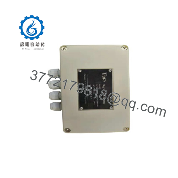
DSC-18-220V
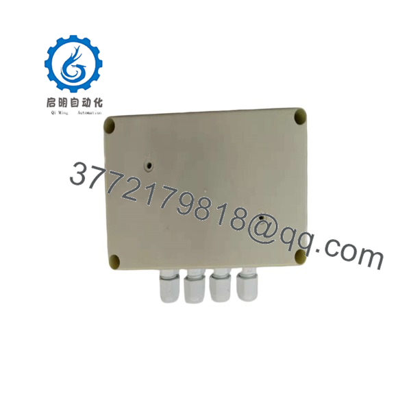
DSC-18-220V
Installation & Configuration Guide
Stage 1: Pre-Installation Preparation
- Safety First: Disconnect all main power feeds to the enclosure. Lock out/tag out the supply circuit breaker. Wait at least 5 minutes to allow the internal DC bus capacitors to discharge below 50 V DC before touching terminal screws or wiring connections. Verify zero voltage with a calibrated multimeter across the L1/L2 and DC+ / DC- terminals.
- Tools Required: ESD wrist strap, PH1 and PH2 screwdrivers, 5.5 mm nut driver, Fluke 115 multimeter, wire marker tags, smartphone for wiring layout capture.
- Data Backup: Connect via RS232/RS485 using DriveTop software to pull and save the running
.parparameter file from the existing drive before unmounting it.
Stage 2: Removing the Old Module
- Unplug the 24 V DC logic power connector and the digital I/O signal plugs.
- Label and remove the motor power leads (U, V, W, PE) and main line input cables. Do not pull on the wiring directly.
- Disconnect the encoder feedback cable by loosening the thumb screws on the D-sub connector.
- Loosen the top and bottom DIN-rail/panel mounting screws, then lift the drive straight out from the cabinet panel.
- Inspect the backplate surface and thermal contact pads for debris, dust build-up, or signs of overheating.
Stage 3: Installing the New Module
- Put on an ESD wrist strap grounded to the cabinet chassis. Verify the replacement unit’s full model code on the side nameplate.
- Configuration Clone: Insert the firmware memory card (if equipped) from the old unit into the top slot of the new drive, or download the saved parameter set using DriveTop software over the serial connection.
- Mount the drive vertically on the enclosure backpanel to ensure proper convective airflow through the cooling fins. Maintain at least 100 mm clear space above and below the chassis.
- Reattach the motor power, main AC input, ground leads, and encoder interface cable. Torque power screw terminals to 0.8 N·m (7.1 in-lbs).
Stage 4: Power-On & Testing
- Measure resistance between input phases L1/L2 and earth ground to confirm no short circuits exist.
- Apply 24 V DC logic control power first. Do not energize main 220 V AC power yet.
- Check the single-digit H1 display status code on the front panel. A display showing
bb(Ready for power supply connection) confirms correct bootup and configuration. - Energize the main 220 V AC line power. The display should transition to
Ab(Drive ready). - Execute a low-speed jog command through your PLC or DriveTop interface to confirm motor rotation direction and feedback resolution before switching to full automatic mode.
⚠️ Troubleshooting Note: If the H1 display shows
F219orF220, check for an open thermal interlock circuit or motor over-temperature fault. AnF860fault indicates an internal converter overload or a mismatch between drive capacity and motor size.
Frequently Asked Questions (FAQ)
Can I swap this drive under live cabinet power?
No. Hot-swapping the DKC DSC-18-220V will result in arcing on the power connectors and can instantly destroy the internal DC bus pre-charge circuitry. Always drop line power and 24 V DC logic power, and wait 5 minutes for the capacitors to fully discharge before disconnecting any terminals.
Is the DKC DSC-18-220V obsolete, and are your units genuinely new?
Yes, the original EcoDrive 01 series is classified as mature/legacy by Bosch Rexroth. However, our stock consists of verified original new-surplus units and fully reconditioned factory spares. Each unit undergoes full component-level inspection, capacitor re-forming (if stored over 2 years), and 24-hour full-load motor testing before shipment.
Will I lose my program logic when I pull the old drive?
The drive holds parameter files (motor profiles, gain settings, I/O mapping), not high-level PLC program logic. If you do not transfer the original parameter set—either by swapping the firmware/parameter card or downloading the .par file via DriveTop—the motor will not commute correctly and will throw a drive configuration fault on power-up.
Can I run a 3-phase 220V input into this drive instead of single-phase?
The DKC DSC-18-220V power stage is designed specifically for single-phase 200–230 V AC input across terminals L1 and L2. You can feed two legs of a 3-phase 200–230 V delta or wye system into it, but do not attempt to wire three phase lines to the power input terminals, as there are only two line terminal connections on the main power block.
What should I do if the replacement drive displays an “F268” code on power-up?
An F268 fault code indicates a parameter checksum error. This happens when a replacement drive has been cleared to factory defaults or powered up with an incompatible firmware card version. You must clear the error by writing a valid parameter dataset tailored to your specific MKD/MKE motor part number using DriveTop software via the serial interface.
Why is your price lower than purchasing through traditional OEM distribution?
OEM channels place high premiums and long lead times on legacy, out-of-production series like EcoDrive 01. We source our inventory directly through verified industrial surplus acquisitions, system retrofits, and excess factory spares, passing the cost savings on without sacrificing pre-shipment quality testing or warranty coverage.



