
 WhatsApp: +86 16626708626
 Email:
  Phone: +86 16626708626
Description
Key Technical Specifications
| Parameter | Value |
|---|---|
| Manufacturer | Bosch Rexroth / Indramat |
| Exact Type Code | DKC10.3-018-3-MGP-01VRS |
| Material / Part Number | R911295612 |
| Product Family | DKC / ECODRIVE Cs |
| Product Type | Servo drive controller |
| Series | 10 |
| Design Version | 3 |
| Rated Current | 18 A |
| Nominal DC-Bus Voltage | 300 V DC |
| Input Phases | 3 |
| Maximum Input Current | 3.1 A |
| Maximum Output Current | 4.3 A |
| Maximum Output Frequency | 300 Hz |
| Maximum Output Voltage | 116 V |
| Firmware | MGP, Multi-Interface General Purpose |
| Firmware Version | 01VRS |
| Interface Option | 10 |
| Protection Rating | IP20 |
| Dimensions | 70 × 182 × 170 mm |
| Weight | Approx. 2.1 kg |
| Maximum Installation Altitude | 2,000 m |
| Maximum Ambient Temperature | 55 °C with applicable derating |
| Relative Humidity | Up to 90% |
| Mounting | Cabinet mounting |
| Associated Communication Card | ECM01.1-DN01 |
| Communication Card Part Number | R911295614 |
The published technical data identifies the unit as an 18 A, 300 V DC-bus DKC controller, with dimensions of approximately 70 × 182 × 170 mm and a mass of about 2.1 kg.
One important sourcing detail: a documented unit with this exact type code is fitted with the ECM01.1-DN01 master communication card, part number R911295614. Do not assume every used or surplus unit has the same communication hardware installed. Verify the card and connector configuration from the actual unit before purchasing.
Product Introduction
The Bosch Rexroth Indramat DKC10.3-018-3-MGP-01VRS is an ECODRIVE Cs servo drive controller designed for single-axis and multi-axis motion applications. It carries an 18 A rated-current class, 300 V nominal DC bus, Series 10 hardware, and MGP-01VRS general-purpose multi-interface firmware.
This drive is commonly encountered in legacy machine automation where the controller, motor, feedback system, firmware, and communication interface must remain matched. The exact type code matters; a visually similar DKC unit is not automatically a valid replacement.
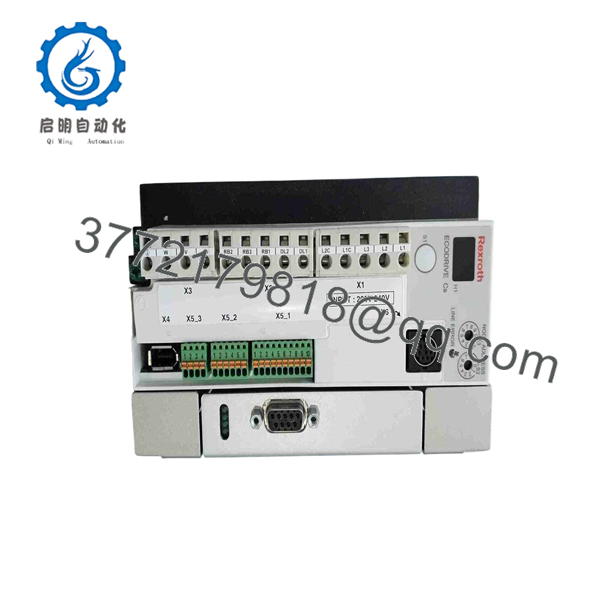
DKC10.3-018-3-MGP-01VRS
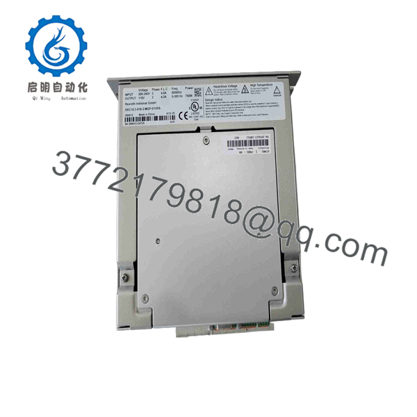
DKC10.3-018-3-MGP-01VRS
Installation & Configuration Guide
Stage 1: Pre-Installation Preparation — 10–20 Minutes
⚠️ Safety First: This is a high-voltage servo drive. Put the machine into its approved safe state, isolate the incoming power, apply LOTO, and follow the applicable Rexroth DC-bus discharge procedure. Never assume the DC bus is discharged simply because the incoming AC power has been switched off.
Tools Required
- ESD wrist strap
- Properly rated multimeter
- Insulated screwdrivers
- Wire labels
- Camera or smartphone
- Torque-controlled screwdriver where required
- Current Rexroth ECODRIVE documentation
Data Backup
- Record the complete DKC10.3-018-3-MGP-01VRS type code.
- Photograph the nameplate and material number.
- Record R911295612 if present.
- Photograph all power, motor, feedback, and control connections.
- Record the installed master communication card.
- Save the existing drive parameters.
- Record the connected servo motor model and feedback type.
- Record existing diagnostic codes before removing the drive.
⚠️ Do not treat the MGP-01VRS suffix as a generic software label. Firmware and communication configuration are part of the replacement decision.
Stage 2: Removing the Old Drive — 10–15 Minutes
- Place the machine in its approved maintenance condition.
- Disconnect and lock out the incoming power.
- Wait the period specified by the Rexroth documentation for DC-bus discharge.
- Measure the DC bus with an appropriately rated meter.
- Do not proceed until the measured voltage is within the site’s approved safe limit.
- Label incoming power conductors.
- Label motor power connections.
- Label feedback and control connections.
- Photograph connector positions and cable routing.
- Disconnect cables without pulling on the conductors.
- Remove cabinet mounting hardware.
- Remove the drive while supporting its approximately 2.1 kg weight.
⚠️ Retain the original drive until commissioning is complete. Its firmware, communication card, parameter memory, and nameplate provide valuable reference information.
Stage 3: Installing the New Drive — 10–15 Minutes
- Verify the replacement marking: DKC10.3-018-3-MGP-01VRS.
- Verify material number R911295612 where applicable.
- Compare the installed communication card with the original.
- Verify the motor model and feedback system.
- Mount the drive securely in the control cabinet.
- Maintain appropriate cabinet ventilation.
- Connect protective earth.
- Reconnect incoming power.
- Connect motor output wiring.
- Connect feedback wiring.
- Reconnect control and communication interfaces.
- Verify shielding and grounding against the original installation and Rexroth documentation.
Self-Checklist
- Exact type code confirmed
- R911295612 verified
- 18 A current class confirmed
- 300 V DC-bus class confirmed
- firmware identified
- Communication card verified
- Motor model verified
- Feedback connection verified
- PE connection secure
- Motor wiring secure
- Control wiring secure
Stage 4: Power-On & Testing — 15–30 Minutes
- Perform a complete wiring inspection before energizing.
- Restore control power according to the approved startup sequence.
- Check the drive display and diagnostic state.
- Verify the installed firmware identification.
- Confirm the communication interface is recognized.
- Verify the motor parameters against the actual motor nameplate.
- Verify feedback operation.
- Check the drive for initialization faults.
- Enable the axis at low speed.
- Confirm rotation direction.
- Compare commanded and actual velocity/position.
- Perform a controlled machine-cycle test.
- Monitor drive current and temperature during the first operating cycle.
⚠️ Do not repeatedly reset an unexplained drive fault. Record the diagnostic information first. A communication-card mismatch, motor parameter error, feedback problem, or incorrect firmware can produce symptoms that look like a drive failure.
The DKC10.3-018-3- is documented for cabinet mounting, with an optimum ambient temperature below 45 °C and maximum installation altitude of 2,000 m. Output capability may require derating when environmental conditions exceed the specified optimum range.
Frequently Asked Questions (FAQ)
What is the rated current of the DKC10.3-018-3-?
The documented rated-current class is 18 A. Do not confuse this type-current designation with every possible operating current or motor rating. The complete motor/drive combination still has to be checked against the application.
What does mean?
The unit is documented with Multi-Interface General Purpose firmware, version 01. The exact firmware configuration matters when replacing an installed drive because the controller’s communication and motion-control functions depend on the installed firmware and associated hardware.
What is the material number for this drive?
The documented material number is R911295612. The communication card associated with a documented configuration is ECM01.1-DN01, R911295614. Verify both against the physical unit because used and surplus drives can be configured differently.
Can I replace it with another drive?
Not automatically. Match the complete type code, rated current, DC-bus class, firmware, communication card, motor, feedback system, and parameter configuration. A unit with a different current code or firmware can require a different commissioning procedure.
Is this drive suitable for a 750 W motor?
Supplier documentation identifies compatibility with 750 W motor applications, but the motor must still be matched using the actual Rexroth motor/drive combination data. Check rated current, feedback, winding data, brake, and motor temperature monitoring before commissioning.
What condition should I expect when buying a replacement?
Do not assume all market listings represent the same condition. Current sources show this exact model offered through new-stock, surplus, repaired, exchanged, and used channels. One current listing specifically identifies a unit as used and in excellent condition, while another offers repair and exchange services. Ask for the actual unit’s nameplate photographs and test status before placing an order.
Does the replacement include the communication card?
Verify this before purchase. A documented .3-018-3- configuration includes the ECM01.1-DN01 master communication card, but at least one market listing warns that terminal blocks are not included. Accessories and communication hardware should therefore be confirmed against the actual inventory unit rather than assumed from the base type code.



