
 WhatsApp: +86 16626708626
 Email:
  Phone: +86 16626708626
Description
Key Technical Specifications
| Parameter | Value |
| Input Channels | 15 Configurable Digital Inputs |
| Output Channels | High-side Switching Digital Outputs |
| Supply Voltage | 18 V DC to 32 V DC (24 V Nominal) |
| Communication | CAN-bus (System Bus compatible) |
| Mounting Type | 35 mm DIN-rail |
| Connector Type | Removable Terminal Blocks (Spring or Screw) |
| Operating Temp | -25 °C to +70 °C |
| Housing Material | High-impact Industrial Polymer |
| Status Indicators | Individual Channel LEDs |
Product Introduction & Supply Chain Strategy
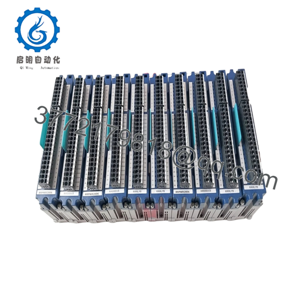
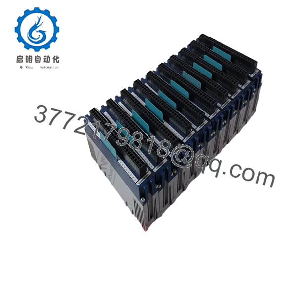
The Rolls-Royce RRDIO15 is a high-density digital interface module used primarily within MTU ADEC and Blue Vision control architectures. It acts as the bridge between field-level binary signals—such as pressure switches, level sensors, and solenoid valves—and the central processing unit. By offloading I/O processing to the RRDIO15, the system maintains high-speed control loops for engine governing and protection.
Integrating New Surplus RRDIO15 modules into your inventory is a high-ROI strategy for maintenance managers. Because these modules are often located in junction boxes subject to thermal cycling and vibration, they are common failure points. Utilizing “New Surplus” ensures that the internal opto-isolators and relays have zero hours of electrical wear. This mitigates the risk of “nuisance trips” associated with refurbished hardware, where aged components can provide unstable signal readings that trigger false engine shutdowns.

- RRDIO15
- RRDIO15
Installation & Configuration Guide
Stage 1: Pre-Installation (Prep & Safety)
Power down the control cabinet and verify the absence of voltage on the 24 V rails. Use a grounded ESD wrist strap before handling the RRDIO15. Document the wire labeling on the existing terminal blocks; if the existing unit uses removable terminals, verify they are compatible with the new hardware to save rewiring time.
Stage 2: Removal
Using a small flat-head screwdriver, release the DIN-rail tension clip at the bottom of the module. Tilt the unit upward and remove it from the rail. Carefully unplug the CAN-bus connector and power leads, ensuring no wires are strained.
Stage 3: Installation (Clone & Seat)
Hook the top of the RRDIO15 onto the DIN-rail and snap the bottom into place. Verify that the module is seated firmly and does not slide. Reconnect the terminal blocks and CAN-bus interface. If the module uses rotary switches or jumpers for Node ID addressing, set them to match the original unit exactly.
Stage 4: Power-On & Testing
Apply 24 V DC power. The green “Power” or “Status” LED should illuminate. Observe the individual I/O LEDs as the engine control system initializes; the module should show active communication with the master ECU. Perform a “Lamp Test” or toggle a known input to confirm the signal is reaching the HMI.
Firmware/Software Versions & Upgrade Notes
The RRDIO15 is generally a “slave” device, meaning its behavior is dictated by the master controller’s configuration. However, ensure the hardware revision (often printed on the side label) is compatible with your current system bus speed. While most RRDIO15 modules are backward compatible, mixing extremely old firmware versions with new ADEC controllers can occasionally lead to CAN-bus “bus-off” errors during high-traffic diagnostic sessions.
Frequently Asked Questions (FAQ)
- Are these modules genuinely new?
Yes. These are New Surplus units, meaning they have remained in original packaging and have never been commissioned in a live engine environment.
- Do I need to program the RRDIO15 specifically?
The RRDIO15 usually requires a Node ID address to be set (via hardware switches or software) so the master ECU can recognize it. Once addressed, the master controller pushes the necessary configuration to the module.
- Can I replace an RRDIO12 with an RRDIO15?
The RRDIO15 offers higher density, but they are not always a direct drop-in replacement due to different wiring footprints and software mapping. Always check your specific system schematic before attempting an upgrade.
- Why not just buy a used module for half the price?
Digital I/O modules contain relays and opto-couplers that have a finite number of cycles. A used module may look fine but fail shortly after installation due to contact pitting or component fatigue. New Surplus provides the reliability of a new part at a significantly lower TCO.
- Is the RRDIO15 hot-swappable?
It is not recommended. Removing or inserting the module while the CAN-bus is active can cause a communication spike that may temporarily trip other modules on the same network.
- What is your return policy if the module doesn’t fix my fault?
We offer a 1-year warranty on the hardware itself. If the module is found to be defective, we will replace it. We recommend verifying your diagnostic codes to ensure the RRDIO15 is the confirmed point of failure before installation.


