
 WhatsApp: +86 16626708626
 Email:
  Phone: +86 16626708626
Description
Key Technical Specifications
| Parameter | Value |
|---|---|
| Manufacturer | SAM Electronics |
| Model | EMP2200 / EMP2200-M |
| Part Number | 815.001.200.01 for documented EMP2200-M system |
| Product Type | Engine Manoeuvring System |
| Primary Application | Marine main engine remote control |
| System Location | Bridge / ECR / Local Control Station |
| Control Functions | Start/stop, control-location selection, slowdown, shutdown |
| Communication | RS-485-based control architecture |
| Interface Functions | Digital input monitoring and relay output control |
| Operator Interface | LCD display and multifunction keypad on documented EMP2200-M system |
| Alarm Functions | Alarm indication, handling and acknowledgement |
| System Role | Main propulsion engine control and monitoring |
| Manufacturer Status | Legacy marine automation equipment |
| Exact Electrical Ratings | Verify from vessel-specific documentation |
| Exact I/O Count | Verify against the installed EMP2200 revision |
| Exact Supply Voltage | Verify against nameplate/datasheet |
| Exact Dimensions | Verify against the physical assembly |
Technical-data caution: Public sources provide useful identification and functional information for EMP2200-M, but I could not verify an authoritative OEM datasheet establishing exact supply voltage, complete I/O count, dimensions, or environmental ratings for every variant. Those values should not be copied from generic listings into an installation specification.
Product Introduction
The SAM Electronics EMP2200 is a marine Engine Manoeuvring System used for remote operation and monitoring of a ship’s main propulsion engine. The documented system provides operator control from locations such as the navigation bridge and Engine Control Room, with functions including engine commands, alarm handling, control-location selection, slowdown and shutdown.
The system combines an operator panel with a controller and field interfaces. Public equipment documentation identifies RS-485 communication, relay outputs, digital inputs, LCD indication, and keypad control as part of the documented -M architecture.
Installation & Configuration Guide
Stage 1: Pre-Installation Preparation — Approx. 30 minutes
⚠️ Safety First
This equipment can be part of the main propulsion control chain. Replacement should therefore follow the vessel’s approved maintenance and machinery-control procedures.
- Obtain permission from the vessel’s engineering/operations team.
- Establish the approved engine maintenance state.
- Follow the vessel’s lockout/tagout and electrical isolation procedure.
- Prevent unintended engine starting or propulsion commands.
- Confirm that associated control power has been isolated before disconnecting wiring.
Tools Required
- ESD wrist strap
- Digital multimeter
- Insulated screwdrivers
- Wire labels
- Camera or smartphone
- Vessel wiring diagrams
- Existing documentation
Data Backup
Before removing the existing unit:
- Photograph the complete front and rear assembly.
- Record the exact model and part number.
- Record PCB revision and serial number where available.
- Photograph every connector and terminal.
- Record Bridge/ECR/Local control configuration.
- Record alarm and shutdown settings.
- Save the existing configuration if the vessel’s system provides an approved backup procedure.
❗ Do not rely on the generic designation “” alone. The docu system uses the more specific 815.001.200.01 identification. Verify the complete marking on the unit being replaced.
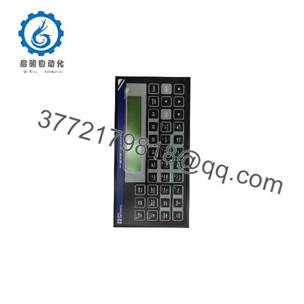
EMP2200
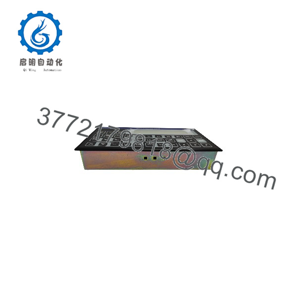
EMP2200
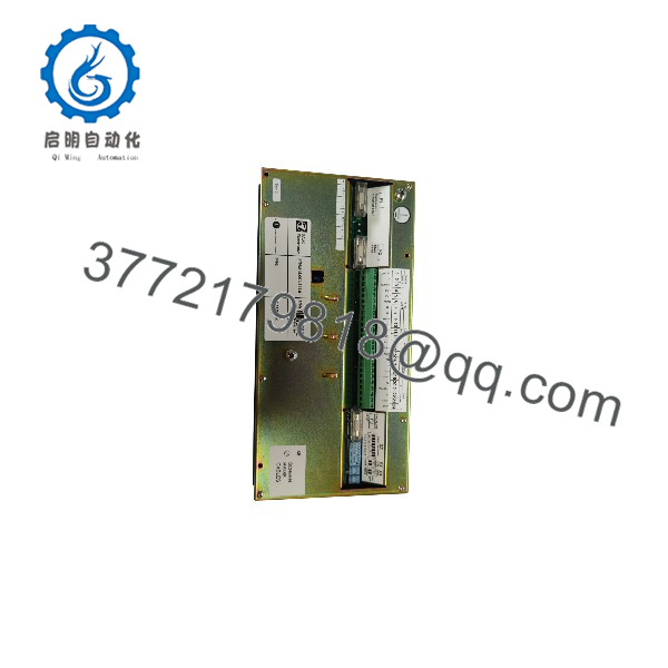
EMP2200
Stage 2: Removing the Old Module — Approx. 15–30 minutes
- Confirm that the engine is in the approved maintenance condition.
- Disable the possibility of an unintended start command.
- Isolate the relevant control power.
- Verify absence of hazardous voltage.
- Photograph the existing wiring.
- Label every connector before removal.
- Disconnect connectors without pulling on the wires.
- Remove the controller or operator panel using the original mounting hardware.
- Inspect connectors for corrosion, loose contacts, moisture, or heat damage.
⚠️ Keep the original unit until commissioning is complete. On legacy marine automation systems, the old unit can provide critical information about wiring, revision, and vessel-specific configuration.
Stage 3: Installing the New — Approx. 20–30 minutes
- Compare the replacement with the original unit.
- Verify:
- Model
- Part number
- Revision
- Connector arrangement
- Hardware configuration
- Use ESD protection when handling internal electronics.
- Install the controller/panel in the original mechanical position.
- Reconnect each connector according to the vessel wiring diagram.
- Verify communication wiring, including RS-485 connections where applicable.
- Verify relay and digital-input wiring.
- Check protective grounding.
- Confirm that no connector is partially seated.
Replacement Checklist
- Exact variant confirmed
- Part number verified
- PCB revision recorded
- Connector positions verified
- RS-485 wiring checked
- Digital inputs checked
- Relay outputs checked
- Grounding verified
- Engine start interlocks verified
Stage 4: Power-On & Commissioning — Approx. 30–60 minutes
- Perform a complete wiring inspection before energization.
- Apply control power according to the vessel’s approved procedure.
- Verify the operator panel/display startup.
- Check active alarms.
- Confirm communication with the associated engine-control equipment.
- Verify Bridge/ECR/Local control selection.
- Test indication of engine status.
- Verify alarm acknowledgement.
- Test slowdown and shutdown logic under the approved commissioning procedure.
- Confirm start/stop command logic without creating an uncontrolled engine start.
- Record all commissioning results.
⚠️ Do not perform a live propulsion test simply because the display and communication link appear normal. sits within a larger engine-control architecture, so command authority, interlocks, feedback signals, and shutdown functions must all be verified.
Frequently Asked Questions (FAQ)
Q1: What is the SAM Electronics ?
The is associated with SAM Electronics marine engine control and manoeuvring equipment. The specifically docu is an Engine Manoeuvring System for remote operation and monitoring of a ship’s main propulsion engine.
Q2: What is the difference betwee?
Public sources do not provide enough OEM documentation to define every difference between generic and var is specifically documented as an Engine Manoeuvring System with part number 815.001.200.01. For procurement, use the complete nameplate and part number rather than assuming that every -marked unit is interchangeable.
Q3: Where used?
It is used in marine propulsion control applications. Documented installation locations include the navigation bridge, Engine Control Room, and local engine-control station.
Q4: What functions do perform?
The documented system provides engine start/stop control, Bridge/ECR control selection, alarm handling, slowdown and shutdown functions, engine-status monitoring, and communication with associated automation equipment.
Q5: Do use RS-485?
Yes. The available product documentation identifies an RS-485-based control architecture for the docu system.
Q6: Is obsolete?
It should be treated as legacy marine automation equipment for procurement planning. Specialized marine suppliers stil equipment, including tested used units, but availability and condition vary.
Q7: Can I replace an wi unit?
Do not assume direct interchangeability. Check the complete part number, PCB revision, connector configuration, vessel application, and software/configuration requirements. A marine engine control system is application-specific, and an apparently similar controller can have different I/O or configuration requirements.
Procurement Note
For a purchase request, specify the complete identification from the existing unit, for example:
SAM Electronics EMP 2200-M — P/N 815.001.200.01
Also request clear photographs of the front panel, rear connectors, nameplate, PCB revision, and serial number. This is more reliable than purchasing from the generic search term “” alone. The documented 815.001.200.01 identification is directly associated wi system in multiple current equipment listings.



