
 WhatsApp: +86 16626708626
 Email:
  Phone: +86 16626708626
Description
Specifications
| Parameter | Specification |
|---|---|
| Model | AVM234SF132 |
| Manufacturer | SAUTER / Fr. Sauter AG |
| Product Type | Electric valve actuator |
| Series | AVM 234S |
| Positioner | SUT electronic positioner |
| Supply Voltage | 24 VAC/DC |
| Actuating Force | 2,500 N |
| Stroke | 0–49 mm; automatic adaptation from 8–49 mm |
| Running Time | 2 / 4 / 6 s/mm |
| Control Signal | 0–10 V, 4–20 mA, 2-point, 3-point |
| Power Consumption | 10 W / 20 VA |
| Protection Rating | IP66 |
| Protection Class | III |
| Weight | 4.1 kg |
| Valve Compatibility | VQD/BQD, VQE/BQE, VUG/BUG, VUP, VUS/BUS; V6R/B6R with mounting set |
| Manual Adjustment | Integrated crank handle |
| Mounting | Upright to horizontal; not suspended |
SAUTER’s documentation identifies the AVM234SF132 as a 2,500 N valve actuator with SUT positioner, operating from 24 VAC/DC and supporting 0–10 V, 4–20 mA, 2-point, and 3-point control. The published data also specifies a 0–49 mm stroke range, 2/4/6 s/mm running-time settings, 10 W/20 VA consumption, and IP66 protection.
Product Introduction
The SAUTER AVM234SF132 is an electrically driven valve actuator designed to position compatible 2-way and 3-way valves. It uses SAUTER’s SUT electronic control system and provides up to 2,500 N of actuating force, with automatic adaptation to the installed valve stroke.
The actuator accepts continuous or switched control depending on the installed configuration. The manufacturer documentation lists 0–10 V, 4–20 mA, 2-point, and 3-point control options, while coding switches allow selection of operating characteristics and running time.
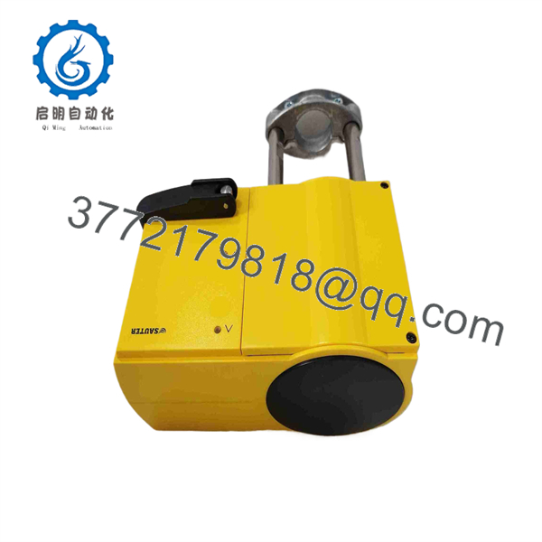
AVM234SF132
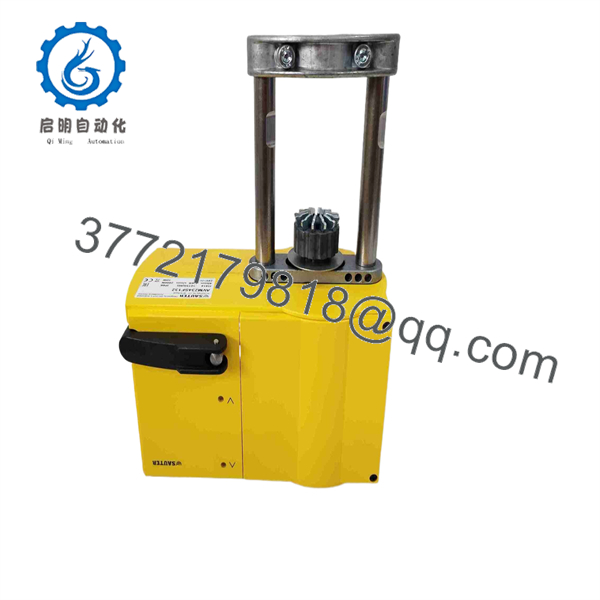
AVM234SF132
Installation Guide
Stage 1 — Pre-Installation
- Apply the site’s lockout/tagout procedure and isolate the 24 VAC/DC control supply.
- Confirm the valve body and actuator combination before removal.
- Record the existing actuator’s wiring, control signal, operating direction, and mounting position.
- Verify that the replacement is AVM234SF132, not AVM234SF132-5, -6, or -7; these variants have different application configurations.
- Check valve stroke requirements against the actuator’s 8–49 mm automatic adaptation range.
- Inspect the valve spindle, coupling, mounting hardware, and actuator housing before installation.
Stage 2 — Remove the Existing Actuator
- Verify that the actuator is electrically isolated.
- Record all terminal connections before disconnecting the wiring.
- Release the actuator from its mounting hardware without forcing the valve spindle.
- Inspect the valve stem for bending, contamination, corrosion, or excessive mechanical resistance.
- Check the mounting bracket and coupling components for wear.
- Confirm that the valve itself moves through the required stroke before fitting the replacement actuator.
Stage 3 — Install the AVM234SF132
- Mount the actuator in the correct orientation; SAUTER specifies installation from vertical upright through horizontal, but not suspended.
- Connect the actuator to the valve using the appropriate mounting hardware.
- Allow the actuator’s automatic spindle connection procedure to operate as specified by the manufacturer.
- Connect the 24 VAC/DC supply and control wiring according to the applicable wiring diagram.
- Verify the selected 0–10 V, 4–20 mA, 2-point, or 3-point control arrangement.
- Set the required characteristic—linear, quadratic, or equal-percentage—where applicable.
- Confirm the desired operating direction before commissioning.
Stage 4 — Power-Up and Functional Test
- Check supply polarity, terminal tightness, and signal wiring before energizing.
- Apply the 24 VAC/DC supply and observe the actuator’s status indications.
- Allow the actuator to detect and adapt to the installed valve stroke.
- Command several intermediate positions rather than testing only fully open and fully closed.
- Verify that the actuator reaches the commanded position without binding or abnormal mechanical noise.
- Confirm the controller’s feedback or operating response where applicable.
- Check the complete valve/actuator assembly under normal operating conditions.
Technical pitfall: Do not substitute the with an -5 or -6 solely because the model numbers are similar. The manufacturer lists the -5 and -6 variants for specific V6R/B6R valve size ranges, so the valve body and mounting configuration must be checked before substitution.
For surplus or refurbished inventory, supplier QC should include visual inspection, actuator movement testing, supply-voltage verification, control-signal response testing, stroke adaptation, mounting inspection, and final identification checks. A supplier should provide an actual test report if these tests are claimed as completed.
FAQ
1. What is the SAUTER ?
It is a 2,500 N electric valve actuator with an integrated SUT positioner, intended for compatible SAUTER 2-way and 3-way valves.
2. What voltage does the require?
The standard is specified for 24 VAC/DC.
3. What control signals are supported?
The published specifications list 0–10 V, 4–20 mA, 2-point, and 3-point control. The exact configuration should be verified against the installed control module and wiring diagram.
4. What is the maximum actuating force?
The provides 2,500 N of actuating force.
5. What is the actuator stroke?
The manufacturer specifies automatic adaptation over an 8–49 mm valve stroke range, with a maximum stroke of 49 mm.
6. Which valves can the operate?
SAUTER documentation lists compatibility with VQD/BQD, VQE/BQE, VUG/BUG, VUP, and VUS/BUS valve series. The can also be configured for V6R/B6R valves with the appropriate mounting set.
7. Is the same as -5 or -6?
No. They are related AVM234S variants, but the manufacturer assigns the -5 and -6 versions to specific V6R/B6R valve applications and size ranges. Confirm the complete valve and actuator part numbers before ordering.



