
 WhatsApp: +86 16626708626
 Email:
  Phone: +86 16626708626
Description
Key Technical Specifications
- Manufacturer: Schenck Process
- Model Number: FGT0200
- Product Family: ROCK legacy control hardware
- Product Type: Control/interface module
- Mounting: DIN rail, subject to confirmation from the installed assembly
- Associated Hardware: Commonly referenced with Schenck FSB U001
- Primary Application: Legacy weighing, feeder, dosing, or process-control installations
- Replacement Requirement: Match the installed FGT0200 marking, base/interface hardware, and wiring arrangement
- Configuration Risk: Verify existing parameter set, addressing, and physical switch/jumper settings before removal
- Service Status: Legacy/obsolete product; availability depends on verified surplus inventory
- Electrical Data: Input supply, I/O assignment, terminal pinout, and communication details must be verified against the installed unit or OEM documentation before purchase
- Documentation Note: Public listings identify the module as part of Schenck’s legacy ROCK hardware environment, but they do not provide sufficiently reliable electrical specifications for safe field substitution.
Product Introduction
The Schenck FGT0200 is a legacy ROCK-system control module used in Schenck Process industrial weighing, feeding, dosing, and material-handling control assemblies. It is commonly encountered in older systems alongside associated hardware identified as FSB U001.
Buyers typically require an exact FGT0200 match to restore an existing machine without a full control-system retrofit. Verify the front-label part number, attached base hardware, terminal arrangement, configuration settings, and installed firmware or parameter data before ordering. Similar-looking ROCK components are not automatically interchangeable.
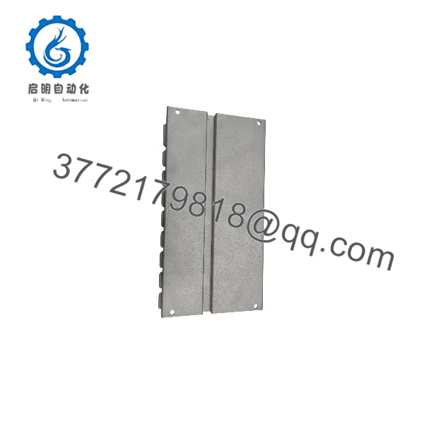
FGT0200
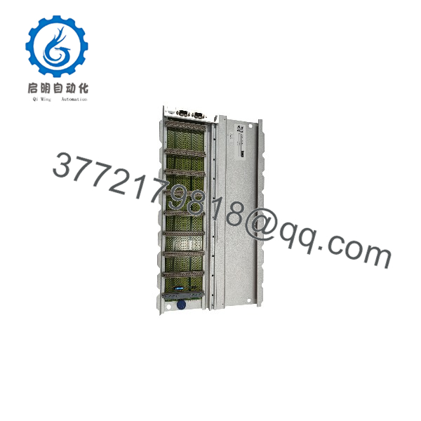
FGT0200
Troubleshooting Quick Reference
| Symptom | Possible Cause | Relevance to This Part | Quick Check Method | Recommendation |
|---|---|---|---|---|
| No LEDs or display activity after power-up | Missing control supply, blown fuse, bad base connection | ❌ Low to medium | Measure the specified supply voltage at the FSB/base input terminals with a Fluke 115 or equivalent; check upstream fuses and DC power supply | Confirm supply voltage and polarity before replacing FGT0200 |
| Module loses communication with the machine controller | Loose connector, incorrect node address, damaged fieldbus cable, configuration mismatch | ✅ Medium to high | Photograph switch settings; inspect connectors; compare bus address and termination to the removed unit; review controller diagnostic log | Do not assume the FGT0200 failed until cabling, address, and termination are verified |
| Feeder or weighing function shows unstable values | Load-cell wiring, shield grounding, failed excitation supply, mechanical binding, parameter corruption | ❌ Usually low | Check load-cell cable shield, excitation and signal wiring; inspect mechanics for material buildup or binding; compare live values against a known test weight | Investigate sensors and mechanics first; replace the module only after proving its signal-processing path is defective |
| Module powers up but system remains in fault state | Missing parameter set, mismatch with companion hardware, interlock active | ✅ Medium | Record all diagnostic LEDs or codes; back up configuration if communications remain available; compare installed companion module numbers | Verify configuration and companion hardware before fitting a replacement |
| Intermittent faults during operation | Loose DIN-rail seating, oxidized contacts, heat, vibration, failing power supply | ✅ Medium | Isolate power; reseat the module and base; inspect contacts for corrosion; monitor supply voltage during machine operation | Correct connection or supply issues before condemning the |
| Replacement unit powers but does not run correctly | DIP switch, jumper, address, or parameter mismatch | ✅ High | Take clear photos of the original module before removal; duplicate every switch position and connector location; restore verified parameters | Treat the replacement as a controlled swap, not a plug-and-play repair |
| Burn marks, odor, or visible component damage | Overvoltage, reverse polarity, wiring error, internal failure | ✅ High | Lock out power; inspect the module, base, and terminal wiring; check for damaged traces, terminals, or heat discoloration | Replace the affected hardware and identify the upstream electrical cause before energizing again |
Field note: This is a legacy module, so external causes are common: power-supply ripple, loose field wiring, missing parameters, and incorrect switch settings can all imitate a failed card. Take a photo of every connector, terminal, and switch before removal. Seriously.
❗ Do not wire from memory. Verify the exact terminal diagram for the installed assembly. A related Schenck ROCK module or a different base unit can have a different pin assignment.
If the diagnosis remains unclear, contact technical support with front-and-rear photographs, the complete label information, companion module part numbers, LED/fault indications, wiring photos, and controller diagnostic logs.
Frequently Asked Questions (FAQ)
Is the Schenck still manufactured?
No. The is generally treated as legacy ROCK-system hardware, so supply normally comes from verified new-surplus, refurbished, or recovered industrial inventory rather than current production. Stock can change quickly, and you should confirm the actual label, quantity, condition, and lead time before releasing a purchase order.
Is a direct replacement for every Schenck ROCK module?
No. It replaces an installed only when the complete hardware arrangement matches. Confirm the full front-label number, any suffix or revision marking, the connected FSB U001 or other companion hardware, terminal layout, installed configuration, and machine wiring. The word “ROCK” alone is not enough to establish compatibility.
Can I hot-swap the ?
Do not assume that you can. For a legacy control module with undocumented site-specific wiring and configuration, remove and install it only with the system safely de-energized unless the OEM documentation for the exact assembly explicitly permits live replacement. Hot-swapping an unsupported module can damage the base, corrupt operating parameters, or create a process fault.
Will I lose programming or calibration during the swap?
Possibly. That depends on where the machine stores configuration, calibration constants, and operating parameters: the , an associated ROCK controller, a separate memory device, or a supervisory system. Before pulling the old part, capture every available setting, including display values, diagnostics, DIP switches, jumper locations, addresses, and parameter backups. I have seen technicians replace a healthy card, restore power, and then spend two days rebuilding feeder calibration because nobody saved the old parameters.
Why does the replacement unit need matching switch and jumper settings?
Factory defaults rarely match the installed machine. Physical settings may define node address, communication speed, termination, signal range, or operating mode. It is the most common rookie mistake, but it happens constantly: take a clear photograph before touching anything, then mirror the old hardware setting by setting.
What condition should I expect from a new-surplus ?
New surplus means an unused original OEM unit from stored inventory, not a newly manufactured product. The box may show shelf wear, old labels, or discontinued packaging, but the module should not show corrosion, rework marks, cracked housings, damaged terminals, or UV yellowing. Ask for actual item photos, label photos, serial-number visibility where appropriate, packaging details, and confirmation of whether the unit was electrically tested.
Why can surplus stock cost less than buying from the original manufacturer?
The product is obsolete, so there is usually no current OEM list price or normal factory support path. The price reflects inventory age, storage history, demand, test level, warranty, and scarcity. Lower price alone is not proof of a better deal. Ask whether the seller verified traceability, inspected terminal condition, tested the module in compatible hardware, documented results, and provides a written warranty.
What testing should a supplier perform before shipping?
For a legacy , ask for documented inbound inspection, serial/label verification, visual inspection, and a functional power-up test in compatible Schenck ROCK hardware where available. A proper process should record LED/boot status, communications or interface checks, load/thermal run time when practical, and final packaging in an ESD-safe bag. Test photos and videos should be available on request. Public marketplace references associate with FSB U001 hardware, so testing should use the correct matching assembly rather than an unrelated generic rack.



