
 WhatsApp: +86 16626708626
 Email:
  Phone: +86 16626708626
Description
Key Technical Specifications
- Manufacturer: Schenck Process
- Model Number: FNT-0050
- Associated Part Number: F201742.01
- Product Family: Multicont
- Product Type: Industrial power supply module
- Primary Function: Provides operating power for compatible Schenck Multicont weighing, dosing, feeder, or process-control electronics
- Nominal Input Voltage: 115/230 V AC
- Permitted Input Tolerance: +10% / −20%
- Input Frequency: 47–53 Hz
- Installation Requirement: Verify the physical module format, rack location, connector arrangement, and terminal assignments against the removed unit
- Output Ratings: Verify output voltage rails, current capacity, ripple limits, and load requirements from the original module label or Multicont documentation before installation
- Lifecycle Status: Legacy/obsolete industrial spare; stock availability depends on verified surplus inventory
Available industrial-stock references identify FNT-0050, associated with F201742.01, as a Schenck Multicont power supply with a 115/230 V AC input range, +10/−20% tolerance, and 47–53 Hz frequency specification. They do not establish reliable output-rail values, so those must be confirmed from the installed equipment or OEM documentation.
Product Introduction
The Schenck FNT-0050, part number F201742.01, is a Multicont-series AC power supply used in legacy Schenck Process control equipment. It converts the available 115/230 V AC mains input into the internal power required by the associated Multicont controller, rack, weighing electronics, or feeder-control assembly.
This part is typically purchased as an exact maintenance replacement when an installed Multicont system has a confirmed power-supply failure. Match the full FNT-0050/F201742.01 identification, mains-voltage setting, module format, output rails, connector layout, and connected load before ordering. It is legacy hardware, so do not substitute a generic DIN-rail power supply without engineering review.
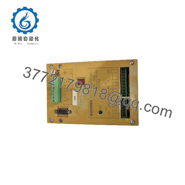
FNT-0050
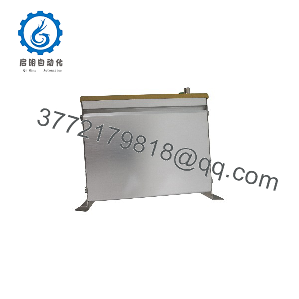
FNT-0050
Troubleshooting Quick Reference
| Symptom | Possible Cause | Relevance to This Part | Quick Check Method | Recommendation |
|---|---|---|---|---|
| Multicont system completely dead | Missing mains supply, open fuse, failed disconnect, bad power supply | ✅ Medium to high | With approved live-work procedures, measure incoming AC at the FNT-0050 input terminals; verify upstream breaker, fuse, isolation switch, and neutral connection | Confirm the incoming supply before replacing the FNT-0050 |
| Supply module has no output | Input present but internal fuse, rectifier, capacitor, regulator, or transformer failure | ✅ High | Disconnect power; inspect for burned odor, heat discoloration, loose terminals, or corrosion; measure specified DC output rails only from verified documentation | Replace the unit if correct input is present and documented output rails remain absent |
| System resets when relays or solenoids energize | Overloaded output, weak power supply, failing bulk capacitor, voltage drop in wiring, external short | ✅ Medium to high | Monitor the output rail with a meter or scope during switching; disconnect nonessential loads under controlled conditions; inspect output wiring for shorts | Identify overloads and short circuits before installing a replacement supply |
| Intermittent faults after cabinet warms up | Thermal failure, loose connector, cracked solder joint, poor cabinet ventilation, power-supply aging | ✅ Medium | Run the system under normal load; observe fault timing; check enclosure temperature and ventilation; gently inspect module seating only with power removed | Improve cooling and connections. Replace only after confirming a supply-related voltage drop |
| Controller powers up but field I/O is dead | Separate field supply failure, blown output fuse, I/O power wiring fault | ❌ Usually low | Check indicator LEDs and measure field supply at the I/O terminals; inspect separate 24 V DC or auxiliary supply modules | Do not replace the until field-power distribution is checked |
| New immediately trips a breaker or fuse | Wiring error, downstream short, incorrect mains setting, defective replacement unit | ✅ Medium | Isolate downstream loads if the system documentation permits; inspect the voltage-selection arrangement; verify 115/230 V supply matches the installed configuration | Do not repeatedly re-energize. Find the short or voltage mismatch first |
| Replacement unit powers the rack but creates unstable readings | Output ripple, grounding problem, incorrect output rail, load incompatibility, unrelated analog-signal issue | ✅ Medium | Compare documented DC rail values under load; check ground continuity; inspect load-cell and analog-cable shielding | Verify electrical compatibility and grounding before declaring the replacement defective |
| Visible swelling, leakage, darkened PCB, or burnt terminals | Internal component failure, heat exposure, overvoltage, contamination | ✅ High | Lock out power; inspect module and rack terminals under adequate lighting; check for contamination and evidence of overheating | Replace the affected module and correct the upstream cause before returning the system to service |
Field warning: A dead Multicont controller does not automatically mean the failed. Check the incoming AC, breaker, fuse, disconnect, terminal tightness, and any separate field-power supply first. I have watched technicians replace a perfectly good power supply when the actual fault was a loose neutral at the cabinet terminal block.
❗ Mains voltage is hazardous. Do not probe the input or open the module unless you are qualified, authorized, and using the site’s electrical-safety procedure. Isolate power, lock out/tag out, verify absence of voltage, and allow internal capacitors to discharge before handling the module.
If the problem remains unresolved, provide technical support with clear photographs of the label, F201742.01 marking, rack position, input terminals, output connectors, visible damage, measured input voltage, documented output-rail measurements, and the connected Multicont module inventory.
Frequently Asked Questions (FAQ)
What is the Schenck used for?
The is a Schenck Multicont power supply module. It supplies internal operating power to compatible legacy Multicont equipment used in weighing, feeding, dosing, and process-control installations. References associate it with part number F201742.01 and specify a 115/230 V AC mains input.
What input voltage does require?
Available stock references specify 115/230 V AC, with a permitted input tolerance of +10% / −20% and a 47–53 Hz frequency range. Before energizing the unit, confirm the installed mains supply and the equipment’s original voltage-selection arrangement. Never assume that a 230 V supply is acceptable simply because the label contains both 115 V and 230 V.
Is still manufactured?
It should be treated as legacy/obsolete industrial hardware. Most available units are likely to be new-surplus, refurbished, or recovered maintenance stock. Confirm actual condition, inventory quantity, lead time, warranty, and test status before planning a plant shutdown.
Can I replace with a generic 24 V DC DIN-rail power supply?
Not without engineering confirmation. The may provide multiple internal rails, specific connector pin assignments, isolation characteristics, grounding references, inrush behavior, and power sequencing required by the Multicont system. A generic 24 V DC supply may physically fit elsewhere in the panel but can damage the equipment or leave the controller unable to start.
How do I know whether the is actually bad?
First confirm correct AC input at the power-supply terminals, including line, neutral, protective earth, fuses, and disconnect condition. Then use the applicable Multicont schematic to measure documented output rails under load. A confirmed input with missing, low, excessive, or unstable documented outputs supports a power-supply diagnosis. Do not guess the output voltages from a similar Schenck model.
Does the replacement retain any Multicont program or calibration data?
Normally, a power supply does not retain application programming or process calibration. Those values are more likely stored in the connected controller, memory module, or engineering system. Still, a low-voltage or interrupted power event can expose battery-backed-memory problems or corrupted configuration in a legacy system. Back up accessible parameters before maintenance and document the machine’s condition before removing power.
Why should I match the .01 number as well as ?
The functional name identifies the product family, while provides a more specific Schenck reference used in inventory listings. Match both markings, along with connector style, physical dimensions, rack position, voltage configuration, and output requirements. This reduces the chance of receiving a similar-looking but electrically different Multicont supply.
What testing should I request for a surplus ?
Ask for actual item photos, label verification, visual inspection for corrosion and rework, a controlled power-up test using the specified input voltage, measurement of documented output rails under load, thermal observation, and written warranty terms. The supplier should use ESD-safe handling for the connected electronics and package the module with terminal and connector protection. Test photos or video should be available upon request.



