
 WhatsApp: +86 16626708626
 Email:
  Phone: +86 16626708626
Description
Key Technical Specifications
| Parameter | Value |
|---|---|
| Manufacturer | Schneider Electric / Modicon |
| Part Number | 140AVI03000 |
| Product Family | Modicon Quantum |
| Product Type | Analog input module |
| Module Format | Standard Quantum I/O module |
| Analog Input Count | 8 differential channels |
| Addressing Requirement | 9 input words |
| Supported Voltage Ranges | 0–5 V DC, 0–10 V DC, ±5 V DC, ±10 V DC |
| Supported Current Ranges | 0–20 mA, ±20 mA; broken-wire detection for 4–20 mA applications |
| Input Resolution | 16 bits for all listed voltage and current ranges |
| Linear Measuring Range | Nominal range × 1.024 V or × 1.024 mA |
| Maximum Input | 50 V DC voltage; 25 mA current |
| Voltage Input Impedance | Greater than 20 MΩ |
| Current Input Impedance | 250 Ω ±0.03% |
| Absolute Accuracy Error | ±0.05% of full scale maximum for voltage; ±0.03% for current |
| Linearity Error | ±0.008% |
| Temperature Drift | ±0.0015% FS/°C typical; ≤ ±0.004% FS/°C maximum |
| Input Filter | Single-pole low-pass; −3 dB at 847 Hz ±20% |
| Common-Mode Rejection | Better than −80 dB at 60 Hz |
| Channel-to-Bus Isolation | 750 V DC or 500 Vrms AC for 60 seconds |
| Channel-to-Channel Isolation | 200 V DC or 135 Vrms AC |
| All-Channel Update Time | 10 ms |
| Fault Detection | Broken wire, 4–20 mA; overrange/undertaking-scale monitoring for 1–5 V use |
| Local Indicators | 8 green channel-on LEDs; 8 red channel-fault LEDs; Active LED; external-fault LED |
| Bus Current Requirement | 280 mA |
| Power Dissipation | 2.2 W |
| External Field Power | Not required by the module itself |
The Schneider Electric 140AVI03000 is an eight-channel, differential Modicon Quantum analog-input module. It supports 0–5 V, 0–10 V, ±5 V, ±10 V, 0–20 mA, and ±20 mA signals at 16-bit resolution, with a 10 ms update time for all channels.
Product Introduction
The Schneider Electric 140AVI03000 is a high-resolution, eight-channel analog input module for Modicon Quantum PLC systems. It reads differential voltage and current signals from field instruments, transducers, speed references, load cells with conditioned outputs, and process-control devices into Quantum controller input words.
This module is selected when the application needs more signal-range flexibility than a basic 4–20 mA card. It handles unipolar and bipolar inputs through ±10 V and ±20 mA, provides 16-bit conversion, and updates all channels in 10 ms. It is a direct Quantum-rack spare, not a direct plug-in replacement for newer Modicon X80 hardware.
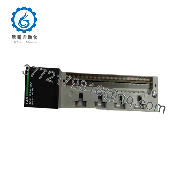
140AVI03000
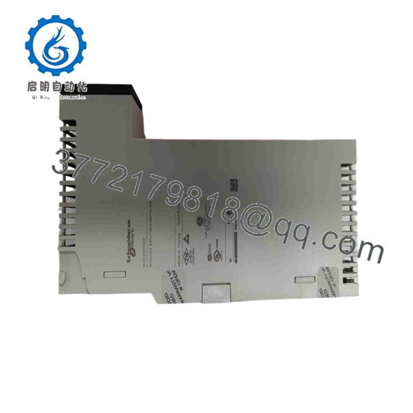
140AVI03000
Troubleshooting Quick Reference
| Symptom | Possible Cause | Relevance to This Part | Quick Check Method | Recommendation |
|---|---|---|---|---|
| All eight channels show zero, invalid, or frozen values | Quantum rack power loss, backplane communication issue, module not fully seated, incorrect PLC hardware configuration, or module fault | ✅ Medium | Check the green Active LED. Verify Quantum power-supply status and controller RUN condition. With power removed, reseat the module and inspect the backplane connector. Confirm the PLC project specifies 140AVI03000 at the installed slot. | Check rack power, backplane health, module seating, and configuration before replacing the module. |
| One 4–20 mA input reports a fault or reads near zero | Open loop, dead transmitter, missing loop power, field fuse fault, broken conductor, incorrect current jumper, or failed channel | ✅ Medium | Measure loop current in series where safe, or measure voltage across the module’s 250 Ω current input. A normal 4–20 mA signal produces about 1–5 V across 250 Ω. Verify transmitter loop power and continuity. | Repair the loop before replacing the card. Broken-wire diagnostics commonly identify field faults, not module failures. |
| One voltage input reads low, high, or out of range | Incorrect source voltage, open sense reference, wiring error, bad transducer, wrong engineering scaling, or failed input channel | ✅ Medium | Measure the signal at the module input and reference terminals with a high-impedance meter. Compare the actual value with the controller’s raw input word and a known-good channel. | Confirm the source, wiring, range, and scaling before replacing the module. |
| Several channels are incorrect immediately after replacement | Wrong part number, current-input jumper error, terminal-block wiring error, PLC configuration mismatch, or incorrect data scaling | ✅ High | Compare old and new module labels. Review every terminal connection and current-input jumper. Confirm the project hardware configuration and scaling function blocks. Inject a known calibrated signal into one channel at a time. | Correct wiring and configuration before making calibration changes. A replacement module should not need software compensation for basic scaling errors. |
| Input value is noisy or fluctuates | Ground loop, incorrect shield termination, loose terminal, unstable transmitter, analog cable routed near VFD conductors, or external electrical noise | ❌ Low to Medium | Measure the source signal at the field device and at the module. Check shield termination and analog reference wiring. Inspect cable routing near motor leads, contactors, SCR systems, and high-current conductors. | Correct field grounding, shielding, and cable routing. The 847 Hz filter is not a substitute for proper analog installation practice. |
| Current signal reads correctly at the transmitter but not in PLC | Open signal conductor, poor terminal contact, current-input resistor/jumper issue, damaged terminal block, or failed input channel | ✅ Medium | Measure at the field transmitter, then at the module-side terminals. Check terminal torque and inspect for broken strands. Verify the correct current-input connection method for the installed terminal block. | Repair the cable or terminal issue first. Replace the module only if a known-good signal fails on that same channel. |
| Active LED is normal but external-fault LED is red | One or more channel-level faults, broken 4–20 mA loop, range violation, field wiring issue, or module defect | ✅ Medium | Locate the illuminated red channel-fault LED. Read the diagnostic word and check that channel’s transmitter supply, signal, reference, wiring, and configured range. | Treat the external-fault LED as a field-side diagnostic starting point. It does not automatically indicate a failed module. |
| HMI value updates slowly but raw PLC value changes | HMI polling delay, PLC scan time, program filtering, analog scaling block, force, or network issue | ❌ Low | Compare the actual field signal with the raw input word and final HMI tag. Check for software averaging, deadband logic, scan-time issues, and active forces. | The module updates all channels in 10 ms. If raw values respond but the HMI does not, troubleshoot logic or communications. |
| Module or channel fails after lightning, ground fault, or field-wiring work | Excess voltage, misapplied field voltage, damaged transmitter, incorrect grounding, or module input damage | ✅ High | Remove power according to site procedures. Inspect the terminal block and field wiring for damaged insulation. Verify no voltage above the specified 50 V DC maximum reaches voltage inputs and no current exceeds 25 mA. | Correct the external cause before replacing the module. Otherwise, the replacement can fail on first startup. |
❗ Range warning: The 140AVI03000 accepts several voltage and current ranges. Do not scale a ±10 V transducer as 0–10 V, and do not treat a 4–20 mA transmitter as a raw 0–20 mA process range unless the PLC application intentionally handles live-zero detection.
❗ Current-loop warning: For a 4–20 mA loop, measure the actual loop current or the voltage across the 250 Ω current input. Four milliamps should be approximately 1 V and 20 mA should be approximately 5 V. This quick check separates a field-loop fault from a PLC input problem.
❗ Wiring warning: Take photos of terminal connections before removing the old card. Do not wire from memory. Analog polarity, common reference, shield treatment, and current-input jumper placement matter.
❗ ESD warning: Use a grounded wrist strap and ESD shielding bag. I have seen an analog module handled in a dry cabinet go back into service, pass a quick checkout, and then develop an intermittent channel fault after production restarted.
If diagnosis remains uncertain, contact technical support with the Quantum CPU model, rack power-supply model, installed slot number, PLC diagnostic words, LED photos, field signal readings at the terminal block, full wiring photos, and the complete 140AVI03000 label. Keep these checks in mind and you will save yourself 90% of typical rework time.
Frequently Asked Questions (FAQ)
What signals can the Schneider 140AVI03000 read?
The 140AVI03000 supports eight differential analog inputs. It accepts 0–5 V, 0–10 V, ±5 V, ±10 V, 0–20 mA, and ±20 mA ranges. It can also support 4–20 mA applications, including broken-wire detection for that live-zero current-loop use case.
Does the 140AVI03000 have 16-bit resolution?
Yes. The module provides 16-bit analog-input resolution across its published voltage and current ranges. That makes it suitable for applications where a basic 12-bit process-input module does not provide enough usable measurement granularity.
Can I mix voltage and current signals on the same module?
Yes, provided every channel is wired and configured for its intended signal type. The module supports multiple unipolar and bipolar voltage/current ranges. Verify the required terminal arrangement and input configuration for each channel from the Quantum hardware documentation before commissioning.
Is this module interchangeable with 140ACI03000?
No. Both are eight-channel Quantum analog-input modules, but they serve different measurement requirements. The 140ACI03000 is a simpler 12-bit unipolar module focused on 1–5 V and 4–20 mA signals, while the 140AVI03000 supports 16-bit conversion plus 0–5 V, 0–10 V, ±5 V, ±10 V, 0–20 mA, and ±20 mA ranges. They may fit the same rack family, but PLC configuration, wiring, scaling, and application signal requirements differ.
Can I hot-swap the 140AVI03000?
Do not assume it is safe to hot-swap. Removing an analog-input module during operation can cause a loss of process values, generate channel faults, or create unsafe control actions. Place affected loops and logic in a safe state, follow your site’s maintenance procedure, photograph field wiring, and verify rack hot-swap rules before removal.
Is the 140AVI03000 obsolete?
Yes. Schneider Electric lists the 140AVI03000 as discontinued on January 15, 2023, with end-of-service scheduled for December 31, 2030. That makes verified surplus stock, documented test results, and a long-term Quantum migration plan important for plants that still depend on this module.
Why is New Surplus stock cheaper than factory supply?
New Surplus usually comes from unused plant inventory, canceled projects, distributor liquidation, integrator spares, or decommissioned Quantum-system stores. It can be genuine Schneider material, but it is outside the current factory sales channel. Since the part is discontinued, the original packaging may vary and exact stock can move quickly.
A credible supplier should inspect the label, backplane contacts, housing, terminal block, and date code; power the module in a genuine Quantum rack; verify the Active and channel LEDs; test all eight channels using calibrated voltage and current sources; document diagnostic behavior; and provide a written test report. Ask for actual unit photos, warranty terms, quantity confirmation, and shipping lead time before placing the order.



