
 WhatsApp: +86 16626708626
 Email:
  Phone: +86 16626708626
Description
Key Technical Specifications
| Parameter | Value |
|---|---|
| Product Range | Modicon Quantum |
| Product Type | AC Power Supply Module |
| Model | 140CPS11410 |
| Input Voltage | 93–138 VAC / 170–276 VAC |
| Nominal Input | 115/230 VAC |
| Input Frequency | 47–63 Hz |
| Input Current | 1.1 A at 115 VAC / 0.6 A at 230 VAC |
| Bus Current | 8 A |
| Configuration | Standalone / Summable |
| Input THD Requirement | <10% of fundamental RMS value |
| Application | Quantum local or remote I/O power distribution |
| Field Connection | 7-point screw terminal |
| Mounting | Modicon Quantum rack |
| Power Supply Type | AC summable |
| Approx. Weight | 0.65 kg |
The Quantum hardware documentation specifies the 140CPS11410 as a 115–230 VAC, 8 A standalone/summable power supply. The detailed hardware specification gives an input range of 93–138 VAC or 170–276 VAC and a 47–63 Hz operating frequency.
Product Introduction
The Schneider Electric 140CPS11410 is an AC power supply module for the Modicon Quantum automation platform. It accepts 115/230 VAC input and provides up to 8 A of bus current for Quantum rack electronics. Its summable architecture allows power supplies to be combined where the Quantum installation requires additional bus-current capacity.
This is a legacy component, not a current-generation Quantum/X80 product. For an existing Quantum system, retaining the exact 140CPS11410 can avoid an unnecessary platform migration. For new engineering, Schneider identifies BMXCPS4002 as the recommended X80 replacement, but the replacement should be evaluated at the system level rather than treated as a blind plug-in substitution.
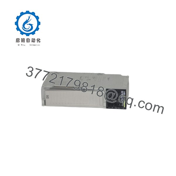
140CPS11410
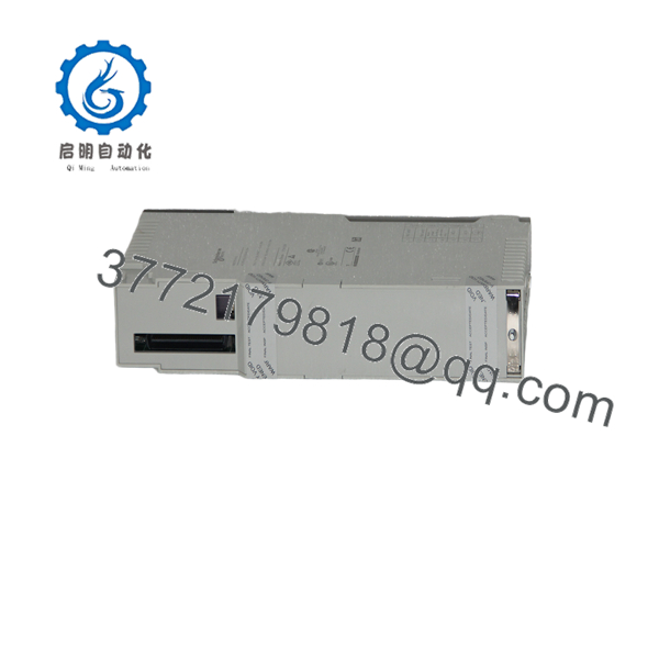
140CPS11410
Installation & Configuration Guide
Stage 1: Pre-Installation Preparation — Approximately 5–10 minutes
⚠️ Safety First: The 140CPS11410 connects directly to AC supply voltage. Place the controlled process in a safe state, isolate the rack, apply lockout/tagout, and verify the absence of voltage before touching the field wiring.
Tools Required:
- ESD wrist strap
- Insulated screwdriver appropriate for the terminal hardware
- Digital multimeter
- Wire labels
- Smartphone or camera
- Existing Quantum hardware documentation
Before removal:
- Confirm the complete part number: 140CPS11410.
- Record the Quantum rack location.
- Photograph the power-supply terminal wiring.
- Record whether the installation uses the module independently or as part of a summable power-supply arrangement.
- Record the incoming supply voltage: 115 VAC or 230 VAC.
- Photograph any voltage-selection jumper arrangement.
- Check the existing Quantum power budget.
- Verify that the replacement has the same part number and required condition.
⚠️ The 115/230 VAC selection matters. Do not change the incoming supply voltage or jumper configuration based on memory. Verify the installation against the applicable Quantum documentation.
Stage 2: Removing the Old Module — Approximately 5 minutes
- Isolate and lock out the AC supply.
- Verify zero voltage at the field terminals with a suitable meter.
- Remove the terminal cover as required.
- Photograph the terminal arrangement.
- Label incoming conductors before disconnecting them.
- Disconnect the AC wiring without stressing the terminals.
- Disconnect any power-loss alarm wiring if fitted.
- Release the module retaining mechanism.
- Pull the power supply straight out of the Quantum rack.
- Inspect the backplane connector for contamination, corrosion, or mechanical damage.
⚠️ Do not reuse a damaged terminal connector. The power supply is handling potentially hazardous AC voltage; loose connections can produce heat and intermittent shutdowns.
Stage 3: Installing the New Module — Approximately 5 minutes
- Wear a grounded ESD wrist strap.
- Verify the replacement is 140CPS11410.
- Confirm the intended supply voltage.
- Check the voltage-selection arrangement against the installation documentation.
- Insert the module into the correct Quantum rack position.
- Make sure the module is fully seated.
- Reconnect the AC conductors according to the original wiring record.
- Secure the terminal connections.
- Reinstall the terminal cover.
- Confirm that no conductor is exposed beyond the permitted termination area.
Self-Checklist:
- Correct 140CPS11410 model
- Correct Quantum rack
- 115/230 VAC configuration verified
- AC L and AC N correctly identified
- Terminal connections secure
- Terminal cover installed
- Summable configuration verified where applicable
Stage 4: Power-On & Testing — Approximately 10 minutes
- Perform a final wiring inspection before energizing.
- Confirm the incoming voltage with the installation documentation.
- Remove personnel and tools from the energized area.
- Restore AC power according to the plant procedure.
- Check the power-supply status indication.
- Verify that the Quantum bus receives power.
- Check the PLC/CPU and I/O modules for normal startup.
- Monitor the rack for abnormal heating, noise, or repeated resets.
- Check the application for power-supply or rack-related diagnostics.
- If the installation uses multiple summable supplies, verify the combined arrangement against the original configuration.
The 140CPS11410 is specifically identified in Quantum documentation as a standalone/summable 8 A supply. It should not be confused with the 140CPS11400, which is also an 8 A Quantum AC supply but has different configuration characteristics.
Important Replacement Note
Schneider Electric currently identifies BMXCPS4002, a Modicon X80 100–240 VAC power supply, as the replacement for 140CPS11410.
That does not mean the BMXCPS4002 should automatically be ordered as a physical replacement without checking the system architecture. The 140CPS11410 belongs to the Quantum platform, while BMXCPS4002 belongs to the Modicon X80 family.
For an operating legacy Quantum plant, first determine whether the requirement is:
- A direct spare for an existing 140CPS11410
- A replacement within an existing Quantum installation
- A broader Quantum-to-X80 migration
- A redesign of the rack power architecture
These are different engineering tasks.
Frequently Asked Questions (FAQ)
What is the Schneider 140CPS11410?
The 140CPS11410 is an 8 A AC power supply module for the Modicon Quantum platform. It operates from a nominal 115/230 VAC source and can operate in standalone or summable configurations.
Is the 140CPS11410 obsolete?
Yes. Schneider Electric lists the part as discontinued. The exact lifecycle dates differ between Schneider regional pages; for example, Schneider UK lists discontinuation on November 1, 2020, while Schneider Netherlands lists February 28, 2002.
For procurement, treat it as a legacy spare and verify actual stock condition rather than assuming factory-new availability.
What is the direct Schneider replacement for 140CPS11410?
Schneider Electric lists BMXCPS4002 as the recommended replacement. It is a Modicon X80 power supply with a 100–240 VAC input specification.
However, this is a platform-level replacement consideration, not simply a statement that BMXCPS4002 is physically interchangeable with the Quantum module.
What is the difference between 140CPS11410 and 140CPS11420?
Both are Quantum AC summable power supplies, but the 140CPS11410 provides 8 A, while the 140CPS11420 is rated for higher bus-current configurations. Quantum documentation identifies the 140CPS11420 with 11 A/16 A/20 A capacity depending on configuration.
Do not substitute one for the other without checking the rack power calculation and system configuration.
Can 140CPS11410 and 140CPS11420 use the same Concept hardware configuration?
Schneider’s own FAQ states that 140CPS11410 and 140CPS11420 are both represented as “114×0” in Concept hardware configuration, with automatic identification; the difference is not caused by an insufficient Concept software version.
That is an important detail for engineers maintaining older Quantum installations.
What input voltage does the 140CPS11410 require?
The nominal input is 115/230 VAC. The published hardware specification gives allowable ranges of 93–138 VAC and 170–276 VAC, with an input frequency of 47–63 Hz.
Why would I buy an original 140CPS11410 instead of migrating to X80?
If the plant has a large installed Quantum base and the immediate requirement is simply to restore a failed power supply, an exact legacy spare can minimize engineering changes, application modification, and outage scope.
For a planned modernization, however, repeatedly buying obsolete Quantum hardware may only postpone the larger migration decision. Compare the spare-parts cost, remaining Quantum lifecycle, downtime exposure, and migration engineering effort before choosing the strategy.
What condition should I specify when purchasing a 140CPS11410?
Specify the condition explicitly:
- Factory Sealed — unopened original packaging
- New Original / New Surplus — unused original equipment outside normal current OEM distribution
- Refurbished (tested) — previously used equipment that has undergone documented testing
Do not accept “new” without clarification. For a critical Quantum spare, request photographs of the actual label, serial number, terminal accessories, packaging, and test documentation. This follows the supplied procurement and quality-control framework, which requires the equipment condition to be stated precisely.



