
 WhatsApp: +86 16626708626
 Email:
  Phone: +86 16626708626
Description
Key Technical Specifications
| Parameter | Value |
|---|---|
| Manufacturer | Schneider Electric / Modicon |
| Part Number | AS-B808-016 |
| Product Family | Modicon 800 Series |
| I/O Type | Discrete AC Output |
| Number of Points | 16 |
| Operating Voltage | 160–260 VAC, 47–63 Hz |
| Output Groups | 2 |
| Outputs per Group | 8 |
| Maximum Continuous Current | 2 A per point |
| Maximum Current per Group | 6 A |
| Maximum Current per Module | 12 A |
| One-Cycle Surge Current | 50 A maximum |
| Maximum Leakage Current | 8 mA at 230 VAC |
| Response Time | 8.3 ms OFF-to-ON; 8.3 ms ON-to-OFF |
| Output Technology | Triac |
| Logic Power Requirement | +5 V at 76 mA; +4.3 V at 480 mA |
| Rack Space | 1 slot |
| Terminal Connector | AS-8534-000 |
| Fusing | One fuse per output group |
| Weight | Approximately 1.25 kg / 2.75 lb |
The published Modicon documentation specifies 160–260 VAC operation, 16 outputs, two groups of eight, 2 A continuous current per point, 6 A per group, and 12 A per module. The same documentation lists an AS-8534-000 terminal connector and one fuse per group.
Compatibility note: Do not treat the AS-B808-016 as a generic 230 VAC digital-output card. Its electrical characteristics, terminal arrangement, rack keying, I/O mapping, and controller configuration must match the installed Modicon 800-series hardware. The Schneider modernization documentation maps AS-B808-016 to BMXDAO1605 for an X80 migration, with specific adapter assemblies.
Product Introduction
The Schneider Electric / Modicon AS-B808-016 is a 16-point discrete AC output module for Modicon 800-series control systems. It switches external 230 VAC loads through two groups of eight outputs and supports up to 2 A continuous current per point.
For legacy installations, the important consideration is electrical and mechanical compatibility rather than simply matching the output count. The module occupies one slot and uses the AS-8534-000 terminal connector. Schneider’s B800-to-X80 documentation provides a defined migration path to BMXDAO1605.
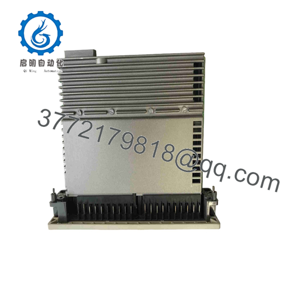
AS-B808-016
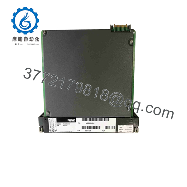
AS-B808-016
Installation & Configuration Guide
Stage 1: Pre-Installation Preparation — Approximately 10 minutes
⚠️ Safety First: The AS-B808-016 switches hazardous AC voltage. Notify operations, place the controlled process in a safe state, apply lockout/tagout, and verify absence of hazardous voltage before touching field wiring.
- Isolate the rack and associated field circuits.
- Wait for the required discharge period specified by the installed system documentation. Do not assume that a five-minute wait alone proves the circuit is safe.
- Wear a grounded ESD wrist strap and work on an ESD-safe surface.
- Prepare a PH1 screwdriver, suitable multimeter, wire labels, terminal tools, and a smartphone or camera.
- Export or otherwise preserve the current PLC application and I/O configuration where the controller architecture permits it.
- Photograph the complete module face, terminal block, slot position, and every field-wire connection.
- Record the existing module’s exact part number and any visible revision or manufacturing information.
❗ Do not rely on memory for the wiring. The B800 terminal arrangement is specific to the AS-B808-016. Schneider documentation identifies dedicated terminal numbering and wiring information for this module.
Stage 2: Removing the Old Module — Approximately 5 minutes
- Verify zero energy with an appropriate meter before disconnecting conductors.
- Remove the front cover or retaining hardware required by the installed housing.
- Label every conductor before removal.
- Disconnect the field wiring carefully. Do not pull on the conductor insulation.
- Release the module’s rack or housing retention mechanism.
- Pull the module straight out to avoid damaging the backplane connector and mechanical keying.
- Inspect the removed module and backplane for:
- Burn marks
- Loose terminals
- Corrosion
- Damaged connector contacts
- Bent or contaminated backplane contacts
- Keep the old AS- beside the replacement until commissioning is complete.
Stage 3: Installing the New Module — Approximately 5 minutes
- Confirm that the replacement is specifically marked .
- Compare the replacement against the old module before installation.
- Confirm the housing keying arrangement and slot location.
- Clone the original terminal arrangement from your photographs.
- Check the two output groups carefully. Each group contains eight outputs and has its own current limitation.
- Insert the module straight into the correct slot.
- Confirm that the module is fully seated and the retaining mechanism is engaged.
- Reconnect field wiring according to the documented terminal assignment.
- Tighten terminals using the applicable terminal manufacturer’s torque specification.
Self-check:
- Exact AS- part number verified
- Correct slot verified
- Terminal wiring photographed and matched
- Output group assignments verified
- Backplane connector clean
- Retaining mechanism locked
- Field wiring secured
Stage 4: Power-On & Testing — Approximately 10 minutes
- Perform a final wiring and short-circuit inspection before energizing.
- Energize the control rack according to the plant’s approved startup procedure.
- Observe module and controller status indications.
- Verify that the controller recognizes the expected 16-point output module.
- Check the configured I/O addresses or memory mapping against the original configuration.
- Command outputs individually during a controlled test.
- Verify the corresponding field device responds correctly.
- Test both output groups rather than testing only the first few channels.
- Monitor abnormal current, fuse operation, unexpected output activation, or thermal behavior.
- Return the process to automatic control only after operations and maintenance personnel approve the test results.
The documentation identifies its output mapping as either 16-bit output mapping or a single register mapping, depending on the programming environment and configuration. Verify the actual application configuration rather than assuming an address scheme.
⚠️ Important replacement trap: A newer architecture is not automatically a plug-in replacement. Schneider identifies BMXDAO1605 as the X80 counterpart for AS-, but the migration requires the appropriate adapter and wiring arrangement.
Quality-Control Inspection for Replacement Stock
For surplus or refurbished industrial I/O, request documented inspection information before installation:
- Inbound inspection: Verify part number, labels, serial information, packaging, connector condition, corrosion, scratches, rework marks, and signs of prolonged storage.
- Functional testing: Test the module in a compatible Modicon 800-series environment where available. Verify output switching across representative channels.
- Electrical testing: Verify applicable supply and isolation parameters using calibrated test equipment. Do not apply a generic hipot procedure unless the manufacturer’s test limits are known.
- Configuration verification: Record revision information and compare mechanical keying and terminal arrangement with the removed unit.
- Final QC: Record test date, inspector, test equipment, and observed condition.
A supplier should be able to distinguish New Original/New Surplus from Refurbished (tested) rather than using “new” as a generic condition label. Current secondary-market listings show multiple conditions for this discontinued part, including refurbished and new-surplus stock.
Frequently Asked Questions (FAQ)
1. Is the Schneider AS- obsolete?
Yes. Secondary-market documentation identifies the AS- as discontinued, and current availability is therefore dependent on remaining inventory and surplus stock.
2. Can I replace the AS- with a BMXDAO1605?
Not as a simple card-for-card swap. Schneider’s modernization documentation identifies BMXDAO1605 as the X80 counterpart, but it also specifies dedicated B800-to-X80 adapter assemblies and wiring arrangements. Treat this as a migration project rather than a direct physical replacement.
3. Can the AS- be hot-swapped?
Do not assume it is hot-swappable. The module controls 230 VAC field circuits, and the published documentation does not provide a blanket hot-swap instruction for this module. Follow the installed Modicon system’s maintenance procedure and isolate hazardous field power before removal unless the exact system documentation explicitly permits another procedure.
4. How much current can each output handle?
Each output supports 2 A continuous, with a documented 50 A maximum one-cycle surge. Each eight-point group is limited to 6 A, while the complete module is limited to 12 A. These limits should be checked against the actual load, especially with contactors, solenoids, and other inductive devices.
5. Will removing the AS- erase my PLC program?
Removing the I/O module does not normally constitute a PLC program erase. The real risk is loss of the application’s expected I/O behavior, configuration mismatch, or an output state changing when the module is restored. Back up the controller application and document the existing I/O configuration before replacement.
6. Is a “new” AS- necessarily factory-new?
No. This is where procurement needs to be precise. The secondary market contains new surplus, refurbished, and other inventory conditions for this discontinued part. Ask for photographs of the actual unit, label information, condition classification, and the seller’s warranty terms before issuing a purchase order.
7. What should I verify before ordering an AS-?
At minimum, verify , the 230 VAC output requirement, 16-point configuration, terminal arrangement, installed Modicon 800-series rack, and required connector. Also confirm whether the required unit must be New Original/New Surplus or whether a tested refurbished unit is acceptable. The AS- uses the AS-8534-000 terminal connector and occupies one rack slot.



