
 WhatsApp: +86 16626708626
 Email:
  Phone: +86 16626708626
Description
Key Technical Specifications
| Parameter | Specification / Value |
| Motor Power Rating | 7.5 kW / 10 HP |
| Input Supply Voltage | 380 V to 500 V AC, 3-Phase (50/60 Hz) |
| Nominal Input Current | 17.6 A at 400 V / 22.7 A at 460 V |
| Continuous Output Current | 17.6 A (Nominal) |
| Output Voltage Range | 0 to 400/460 V AC, 3-Phase |
| Output Frequency Range | 0.5 Hz to 400 Hz |
| Switching Frequency | 2 kHz to 4 kHz default (configurable up to 16 kHz with derating) |
| Transient Overtorque | 170% for 60 seconds, 200% for 2 seconds |
| Efficiency / Power Factor | 97% efficiency |
| Operating Temperature | −10 °C to +40 °C (up to +50 °C with current derating) |
| Dimensions (H x W x D) | 325 mm x 230 mm x 210 mm (12.8 in x 9.0 in x 8.2 in) |
| Weight | Approx. 13 kg (28.6 lbs) |
Product Introduction & Supply Chain Strategy
The ATV58HD12N4 is a heavy-duty 7.5 kW (10 HP) variable frequency drive designed for precise speed control of 3-phase asynchronous induction motors in industrial process applications, including heavy pumps, fans, conveyors, and extruders. It processes 380–500 V AC line input to generate a clean, adjustable-frequency 3-phase output, maintaining smooth torque across full operating ranges.
Procuring the ATV58HD12N4 as New Surplus provides a critical hedge against unplanned downtime in aging automated plants. Refurbished or previously used VFDs present hidden reliability hazards—primarily dried electrolytic capacitors in the DC bus, aged gate drivers, and degraded power semiconductors exposed to thermal cycling. Installing an un-aged New Surplus ATV58HD12N4 preserves maximum mean time between failures (MTBF), fits existing panel footprints without costly mechanical redesigns, and avoids software migration risks associated with upgrading to newer drive platforms.
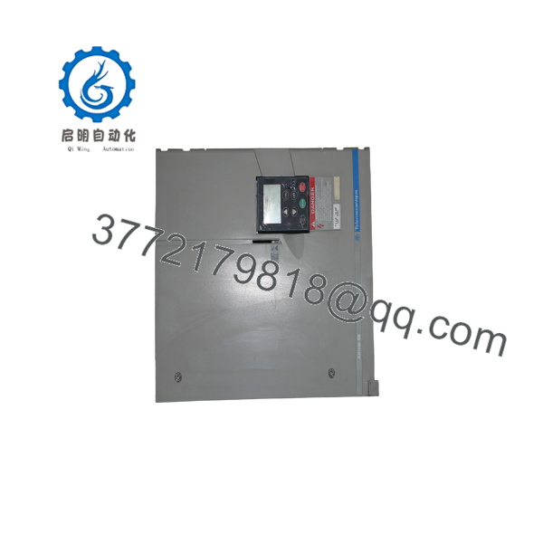
ATV58HD12N4
Installation & Configuration Guide
Stage 1: Pre-Installation (Prep & Safety)
- Execute strict Lock-Out/Tag-Out (LOTO) on the main 3-phase power supply feeding the drive enclosure.
- Put on an ESD-grounded wrist strap and verify insulated safety tools are ready.
- Photograph all terminal wiring connections, dynamic braking resistor leads, control wiring terminal strips, and optional communication cards (e.g., Modbus, Profibus).
Stage 2: Removal
- Wait a minimum of 3 minutes after total power disconnection to allow internal DC bus capacitors to fully discharge. Verify the DC voltage across terminals PA(+) and PC(−) measures below 45 V DC using a calibrated multimeter.
- Label and disconnect power input leads (R/L1, S/L2, T/L3), motor output cables (U/T1, V/T2, W/T3), control wiring, and protective earth (PE) grounding conductors.
- Support the drive’s 13 kg frame, loosen the panel mounting hardware, and carefully remove the drive from the enclosure backplane.
Stage 3: Installation (Clone & Seat)
- Mount the new ATV58HD12N4 vertically on a flat surface, ensuring a minimum clearance of 50 mm above and below the chassis for unimpeded cooling airflow.
- If swapping the keypad/display terminal (VW3A58101) or plug-in options card, carefully align the multi-pin connector and snap into place.
- Terminate motor output and power input cables to exact torque specifications, ensuring shield grounding clamps for motor leads maintain solid 360-degree contact with the grounding plate.
Stage 4: Power-On & Testing
- Re-check line voltage phases across terminals R/L1, S/L2, and T/L3 prior to closing the main breaker.
- Apply line power. Verify the display module powers up cleanly without reporting immediate trip codes (e.g.,
USFundervoltage orOHFoverheating). - Perform a rotation check in manual/local control mode at low frequency (5–10 Hz) before engaging full industrial automation logic.
- Firmware/Software Versions & Upgrade Notes
- Parameter Consistency: Always back up parameters from the existing drive using the VW3A58101 graphic display terminal or Type-H PC software before decommissioning. Upload the saved parameter profile into the replacement ATV58HD12N4 to preserve ramp times, acceleration curves, motor thermal profiles, and custom macro configurations.
- Option Card Compatibility: Ensure optional fieldbus modules (Profibus DP, DeviceNet, Modbus Plus) installed in the old drive match the hardware revision slot on the replacement unit. Standard Altivar 58 main boards accept all legacy V58 series option cards.
- Control Board Revisions: Firmware logic resides on the internal control card. Upgrading or downgrading firmware versions via chip swap requires re-verifying factory motor parameters (like motor nominal voltage, current, and power factor) to ensure correct auto-tuning (TUN) performance.
- Frequently Asked Questions (FAQ)
Q: Are these ATV58HD12N4 drives verified to be original and unused?
A: Yes. We stock strictly New Surplus / Original New inventory. These drives come from verified plant spare reserves and surplus purchases. They feature original factory components with zero operational hours, zero connector pin wear, and no prior field installation.
Q: Why choose New Surplus over a refurbished drive?
A: Refurbished VFDs carry high risks of sudden failure due to degraded internal DC bus capacitors, fatigued power IGBTs, and thermal breakdown of PCB traces. While refurbished units save a small fraction upfront, a single drive failure can trigger tens of thousands of dollars in emergency downtime. Our New Surplus units provide OEM-level longevity and absolute peace of mind.
Q: Can I hot-swap the while the panel is powered?
A: No. Variable frequency drives must never be connected or disconnected while power is applied to the main line terminals or DC bus. Always perform complete Lock-Out/Tag-Out (LOTO) and wait 3 minutes for capacitor discharge before servicing.
Q: Does the replacement come pre-programmed?
A: No. Drives ship with factory default parameter sets. You must input your motor’s nameplate data (Voltage, Frequency, Current, RPM) and transfer operational parameters via the graphic display terminal or PC software prior to run command execution.
Q: What is the warranty coverage on this New Surplus drive?
A: Every unit undergoes thorough physical inspection, visual seal verification, and static electrical checks in our ESD-safe facility prior to shipment. We supply all New Surplus drives with a comprehensive 1-year replacement warranty.



