
 WhatsApp: +86 16626708626
 Email:
  Phone: +86 16626708626
Description
Key Technical Specifications
| Parameter | Specification Value |
| Manufacturer | SEW-Eurodrive |
| Part Number | 8222215.14.17 |
| Product Type | Inverter Control Board Assembly |
| Drive Compatibility | SEW MOVIDRIVE Compact / 60A Series |
| Supply Voltage | 24 VDC ±15% (External backup control supply) |
| Onboard Display | 7-Segment LED Status / Fault Indicator |
| Encoder Interface | Dual Sub-D 9-pin connections (X14 Encoder In/Out, X15 Encoder In) |
| Control I/O Terminals | Removable screw-terminal strips (X10, X11, X12, X13) |
| Operating Temperature | 0 °C to +50 °C (+32 °F to +122 °F) |
| Conformal Coating | Industrial-grade humidity and dust protective coating |
| Dimensions & Weight | Standard MOVIDRIVE internal chassis format |
Product Introduction & Supply Chain Strategy
The SEW 8222215.14.17 is the primary internal control card assembly for SEW MOVIDRIVE 60A series variable frequency drives. Positioned behind the front cover of the inverter, it manages high-speed vector control algorithm execution, encoder signal processing, gate driver firing loops, and communications across option card expansion slots for applications in automated storage systems, gantry cranes, and high-speed conveyors.
This product is a Brand New Surplus unit. It is not used, not pulled from a decommissioned panel, and not refurbished. All cards undergo comprehensive static pin testing, bus interface verification, and visual power-section trace checks to ensure OEM-level performance. Purchasing New Surplus components avoids the severe operational hazards linked to refurbished drive electronics, such as heat-stressed microcontrollers, dried-out surface-mount capacitors, and degraded optocouplers. An intermittent failure on an inverter control board can trigger spurious drive trips (e.g., F08 Speed Monitoring or F14 System Fault), halting continuous conveyor lines and costing thousands of dollars per hour in production delays. Stocking genuine New Surplus cards lowers your Total Cost of Ownership (TCO) while guaranteeing fast recovery during unexpected drive breakdowns.
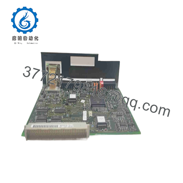
8222215.14.17
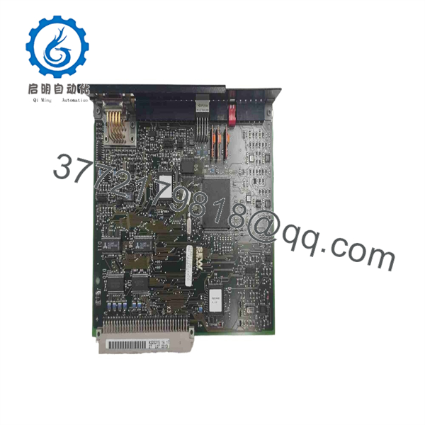
8222215.14.17
Installation & Configuration Guide
1.Pre-Installation Preparation & Safety:Prerequisite Phase.
Disconnect main 3-phase AC power to the MOVIDRIVE unit and perform Lock-Out/Tag-Out (LOTO). Wait at least 10 minutes for the intermediate DC bus capacitors to discharge fully. Put on a grounded anti-static wrist strap. Measure the DC link terminals (+R, -R / +UZ, -UZ) to verify voltage has dropped below 50 VDC before opening the drive casing.
Verification: Confirm zero AC line voltage and safe DC link voltage using a calibrated digital multimeter rated for 1,000 V.
2.Removal of Legacy Control Board:Extraction Phase.
Remove the front DBG keypad or cover plate. Unplug all terminal blocks (X10–X13) and encoder cables (X14, X15) from the board face. Undo the retaining clips or mounting screws securing the board to the internal chassis plastic frame. Carefully lift the board straight forward to disengage the rear multi-pin gate drive connector from the power section.
Verification: Inspect the internal chassis pins and multi-pin power interface socket for heat discoloration or physical contamination.
3.Hardware Transfer & Board Insertion:Physical Mount Phase.
Transfer any socketed parameter chips, system option cards (e.g., PROFIBUS DFP11A or INTERBUS DFI11A), and DIP switch configurations from the old board onto the replacement 8222215.14.17 card. Align the replacement board with the mounting slots inside the MOVIDRIVE chassis and press firmly until the rear connector seats into the power board header. Fasten retaining screws to 0.5 Nm (4.4 in-lb) and re-plug all terminal connectors.
Verification: Ensure the card face aligns flush with the housing and all terminal plugs snap locked into position.
4.Power-On & Parameter Verification:Commissioning Phase.
Re-apply 24 VDC auxiliary control power first without main AC high voltage. Observe the 7-segment LED display on the board face during boot up. The display should cycle through initialization sequences and settle on a ready status code (“0” or “A”). Connect via MOVITOOLS software or DBG keypad to reload drive parameter sets if necessary.
Verification: Confirm the drive communicates error-free, displays correct encoder feedback, and accepts run commands when main line power is restored.
Firmware/Software Versions & Upgrade Notes
- System Integration: Fully compatible with SEW MOVIDRIVE MDV60A and MDF60A control platforms managed via MOVITOOLS Motion Studio software.
- Parameter Transfer: Parameter settings are stored within the drive’s memory module or external DBG keypad. When swapping board 8222215.14.17, move the memory plug or upload/download parameters via MOVITOOLS to ensure identical ramp times, motor data, and I/O assignments.
- Hardware Revisions: Ensure the sub-revision code (14.17) aligns with your original drive build specifications to guarantee full mechanical and electrical pin compatibility with the internal power stage driver board.
Frequently Asked Questions (FAQ)
Q: Is this SEW 8222215.14.17 control board genuine brand new or a refurbished pull?
A: This unit is 100% Brand New Surplus. It has never been installed in an active drive chassis or operated in a plant environment. It comes from clean, verified warehouse storage in protective ESD packaging.
Q: Why is buying New Surplus better than repairing or buying a refurbished SEW drive card?
A: Drive control boards handle continuous thermal loads within drive enclosures. Refurbished or repaired boards frequently retain aging electrolytic capacitors, degraded signal relays, and heat-fatigued circuit traces. Buying New Surplus ensures full original insulation resistance, zero thermal wear, and maximum operational reliability for your critical motion control systems.
Q: Do I need to reprogram the entire inverter after installing this card?
A: The board requires drive parameters to operate the motor correctly. If you transfer the original removable memory module (or pluggable keypad/option module containing the saved configuration) onto the new board, the parameter set transfers automatically. Otherwise, you can download the saved parameter file using SEW MOVITOOLS software.
Q: Can this board be swapped while the drive DC bus is energized?
A: No. Replacing the control card while DC bus voltage or 24 VDC auxiliary power is present will cause arcing across multi-pin headers, destroying both the new control card and the underlying gate driver board. Always verify zero voltage before servicing internal components.
Q: What warranty coverage applies to this SEW card?
A: Every SEW 8222215.14.17 board is visually inspected and electrically verified prior to shipment. We back this part with a full 1-year functional replacement warranty.



