
 WhatsApp: +86 16626708626
 Email:
 Phone: +86 16626708626
Description
Key Technical Specifications
| Parameter | Value |
|---|---|
| Manufacturer | SEW-EURODRIVE |
| Model | MXA81A-100-503-00 |
| Product Family | MOVIAXIS® MX |
| Product Type | Multi-axis servo inverter axis module |
| Rated Output Current at 8 kHz PWM | 100 A |
| Rated Output Current at 4 kHz PWM | 133 A |
| Maximum Output Current | 250 A |
| Nominal DC Link Voltage | 560 V DC |
| Output Voltage | 0 to maximum mains-derived voltage, subject to system configuration |
| Module Size | Size 6 |
| Safety Design | One integrated safety relay |
| Protection Rating | IP10, as listed by third-party product documentation |
| System Integration | MOVIAXIS multi-axis drive system |
| Commissioning Software | MOVITOOLS® MotionStudio; confirm applicable software and firmware requirements |
Sources: SEW-EURODRIVE MOVIAXIS technical documentation and product information from industrial parts suppliers.
Engineering note: The 560 V DC figure refers to the nominal DC link, not a general-purpose external supply input. Confirm the complete drive system’s power supply, DC-link arrangement, motor ratings, and wiring requirements in the OEM manual before connecting the module.
Product Introduction
The SEW-EURODRIVE MXA81A-100-503-00 is a size 6 axis module in the MOVIAXIS multi-axis servo inverter family. It controls a servo motor within a coordinated drive system and provides a nominal output-current rating of 100 A at 8 kHz PWM, increasing to 133 A at 4 kHz PWM. The MXA81A design incorporates one safety relay.
This module is intended for machine systems that require coordinated servo motion, including positioning and synchronized axis control. Replacement planning must account for the existing MOVIAXIS power supply, DC-link configuration, motor and encoder interfaces, firmware, and safety circuit. Verify all ratings and the applicable safety documentation before commissioning.
Installation & Configuration Guide
The MXA81A-100-503-00 operates as part of a MOVIAXIS drive system. It is not a standalone drive that should be connected directly to an arbitrary power source. The steps below provide a preliminary replacement workflow; the applicable SEW-EURODRIVE operating instructions take precedence.
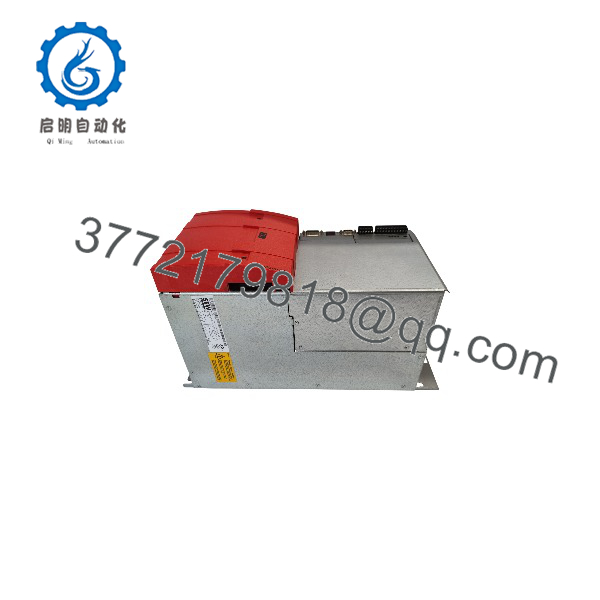
MXA81A-100-503-00
Stage 1: Pre-Installation Preparation
Estimated hands-on time: 15–30 minutes, excluding shutdown and discharge verification.
- Notify operations and secure the machine. Obtain authorization for the shutdown and confirm that the driven machinery is in a safe state.
- Apply lockout/tagout (LOTO). Isolate all relevant power sources, including the drive system’s mains supply and any auxiliary supplies.
- Verify DC-link discharge. The drive can retain hazardous electrical energy after power isolation. Wait for the OEM-specified discharge period and verify the safe voltage level using an appropriately rated instrument.
- Record the full model number, serial number, hardware revision, and any available order-specific identification.
- Photograph the existing module’s wiring, connectors, mounting position, and safety-circuit connections.
- Record motor data, encoder configuration, drive parameters, firmware versions, and fault history where available.
- Confirm that the replacement matches the required 100 A module and the existing system configuration.
Tools and documentation: Appropriate insulated tools, a properly rated multimeter, ESD protection, wire labels, a camera, the applicable MOVIAXIS system manual, and the site’s approved electrical safety procedures.
Stage 2: Removing the Existing Module
Estimated hands-on time: 15–30 minutes, depending on cabinet layout.
- Confirm electrical isolation and verify that the DC link has discharged to the level specified by the manufacturer.
- Label and document all relevant power, motor, encoder, communication, and safety connections.
- Disconnect the wiring using the specified connector-release procedures. Do not pull on cables or force terminals.
- Release the module’s mechanical retention hardware in accordance with the installation manual.
- Remove the module carefully, protecting adjacent equipment and connectors.
- Inspect the mounting area, DC-link connections, terminals, and neighboring modules for signs of overheating, contamination, or mechanical damage.
- Retain the original module until the replacement has been commissioned and verified.
⚠️ Do not remove or insert the axis module while energized. Treat the DC link and connected drive components as potentially hazardous until the prescribed isolation and discharge checks are complete.
Stage 3: Installing the Replacement
Estimated hands-on time: 20–40 minutes.
- Compare the replacement’s full type designation and identification details against the removed unit.
- Verify the DC-link arrangement, motor-current requirements, encoder interface, and system compatibility using the applicable OEM documentation.
- Inspect all mating connectors and terminals. Replace damaged components before installation.
- Install the module in the designated mounting position and secure it using the specified hardware and tightening torque.
- Reconnect power, motor, encoder, communication, and safety wiring according to the verified wiring diagrams.
- Confirm that the safety relay circuit and external safety devices match the machine’s approved safety design.
- Check protective grounding, cable shielding, connector retention, and cabinet clearances.
Pre-commissioning checklist
Stage 4: Power-On and Functional Testing
Estimated hands-on time: 30–60 minutes after installation, subject to system complexity.
- Complete the required electrical inspections before restoring power.
- Verify that the MOVIAXIS power supply and other required system modules are installed and configured correctly.
- Restore power in the sequence specified by the system manual.
- Check module status indicators and diagnostic messages against the OEM documentation.
- Connect the applicable engineering software and verify the module’s identification, parameter set, and firmware compatibility.
- Confirm motor and encoder configuration before enabling motion.
- Test the safety function through the machine’s approved validation procedure. Do not bypass the safety relay or external interlocks.
- Conduct a controlled, low-risk motion test under an authorized commissioning procedure.
- Verify direction of rotation, positioning behavior, fault handling, and communication with the system controller.
- Record the final configuration, diagnostic results, and commissioning approval.
⚠️ If the module reports a fault, do not assume firmware mismatch is the cause. Review the diagnostic code, DC-link status, motor and encoder configuration, and safety-circuit state before making changes.
Frequently Asked Questions (FAQ)
Q1: What is the SEW-EURODRIVE MXA81A-100-503-00 used for?
It is a 100 A MOVIAXIS multi-axis servo inverter module used to control a servo motor within an industrial motion-control system. The module supports coordinated axis control and incorporates one safety relay.
Q2: What is the rated current of the MXA81A-100-503-00?
The documented nominal output current is 100 A at 8 kHz PWM and 133 A at 4 kHz PWM. The maximum output current is listed as 250 A. These figures describe different operating conditions and should not be treated as interchangeable continuous-current ratings. Confirm the applicable thermal and duty-cycle limits in the OEM technical manual.
Q3: Can I replace the MXA81A-100-503-00 with an MXA80A module?
Do not assume the two models are interchangeable. The MXA81A incorporates one safety relay, while the MXA80A has a different safety configuration. A replacement must match the drive-system requirements, safety architecture, current rating, firmware, and applicable hardware configuration. Obtain written compatibility confirmation from SEW-EURODRIVE or a qualified drive-system specialist before substitution.
Q4: Can the MXA81A-100-503-00 be hot-swapped?
Do not treat this module as hot-swappable. Isolate the relevant power sources and verify DC-link discharge before removing or installing it. Follow the applicable MOVIAXIS operating instructions and the site’s electrical safety procedures.
Q5: Does the module require a separate power supply?
The MXA81A operates within the MOVIAXIS multi-axis drive architecture, which uses a compatible supply module and shared DC-link arrangement. It is not intended to operate as an independent, general-purpose servo drive. Verify the supply module, DC-link connections, system configuration, and motor interface before commissioning.
Q6: Is the MXA81A-100-503-00 obsolete, and can I buy it new?
The exact lifecycle status has not been confirmed from an official manufacturer lifecycle notice. Third-party suppliers list the model in several conditions, including new and refurbished units, but advertised condition and stock do not establish OEM authorization or factory-new provenance.
Before purchasing, request:
- A photograph of the actual unit and its nameplate.
- Written confirmation of the unit’s condition.
- Available test reports and serial-number traceability.
- Warranty terms and return conditions.
- Confirmed dispatch lead time.
Q7: What software should I use to configure the MXA81A-100-503-00?
SEW-EURODRIVE identifies MOVITOOLS® MotionStudio among its engineering and startup software offerings. Confirm the software version, firmware compatibility, communication interface, and required project files for your particular MOVIAXIS installation before making parameter changes.



