
 WhatsApp: +86 16626708626
 Email:
  Phone: +86 16626708626
Description
Key Technical Specifications
| Parameter | Value |
| Input Channels | 2 Independent Channels |
| Input Sensor Compatibility | Electro-dynamic velocity transducers or displacement sensors |
| Analog Output | Dual 4-20 mA DC (Internal/External Power Options) |
| Relay Outputs | Alert and Danger (Normally Energized/De-energized selectable) |
| Frequency Range | 10 Hz to 1,000 Hz (Standard velocity configuration) |
| Power Supply | 24 V DC ± 10% |
| Operating Temperature | 0 to +55 °C (32 to 131 °F) |
| Mounting Type | Rack-mounted (VM-5 Series Chassis) |
| Weight | Approximately 450 g (1.0 lb) |
Product Introduction
The Shinkawa VM-5G0-2 is a high-precision dual-channel vibration monitoring module designed for the VM-5 Series Turbine Supervisory Instrumentation (TSI) system. It serves as a critical protection layer for steam turbines, gas turbines, and large centrifugal compressors, providing real-time vibration data and automated alarm triggering.
Engineers specify the VM-5G0-2 due to its high reliability in harsh industrial environments and its straightforward integration into distributed control systems (DCS). Unlike general-purpose vibration transmitters, this module features dedicated hardware for alarm logic, ensuring that machinery protection remains active even if the supervisory communication link fails.
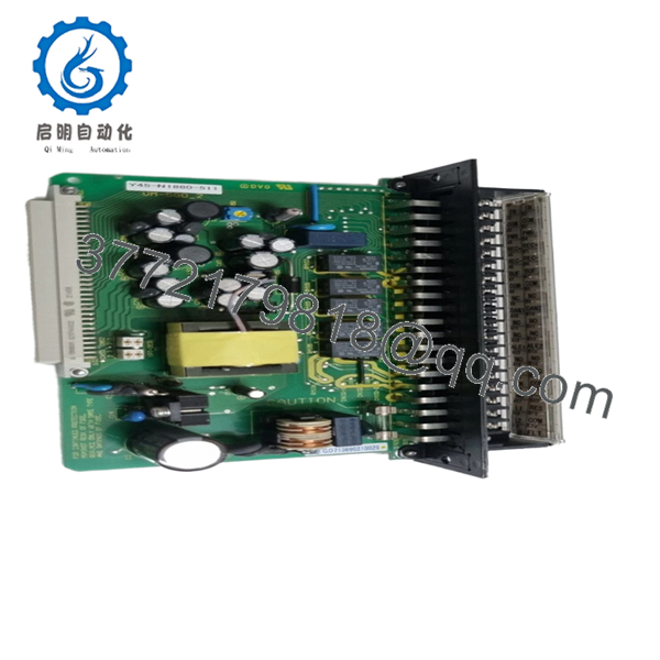
- VM-5G0-2
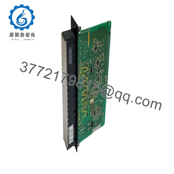
- VM-5G0-2
Installation & Configuration Guide
Stage 1: Pre-Installation Preparation
- ⚠️ Safety First: Coordinate with the control room to bypass vibration trips. Ensure the machine is in a stable state. Verify 24 V DC power availability.
- Tools Required: ESD wrist strap, small flat-head screwdriver (2.5 mm), and a calibrated signal generator for loop testing.
- Data Backup: Record the current Alert and Danger setpoints from the module being replaced. Photograph the rear backplane jumpers if accessible.
Stage 2: Removing the Old Module
- Loosen the two captive thumb screws on the front panel.
- Carefully pull the module forward using the integrated handle.
- ⚠️ Note: Avoid touching the edge connector pins to prevent ESD damage or contamination from skin oils.
- Inspect the rack slot for any debris or bent pins that could obstruct the new module.
Stage 3: Installing the New Module
- ESD Prep: Wear your grounded strap.
- Configuration Clone: Check the side-mounted DIP switches or jumpers. These define the input sensitivity (e.g., 20 mV/mm/s) and relay logic. Replicate the settings from the old unit exactly.
- Align the module with the guide rails in the VM-5 rack.
- Slide the unit in firmly until the faceplate is flush with the rack.
- Tighten the thumb screws to ensure a solid ground connection through the frame.
Stage 4: Power-On & Testing
- Apply power to the rack. The “OK” LED should turn green after a brief self-test.
- Observe LEDs: If the “FAULT” LED illuminates, verify the sensor loop integrity; the VM-5G0-2 monitors for open/short circuits in the transducer lines.
- Signal Injection: Use a simulator to inject a signal equivalent to 50% of the scale. Verify the 4-20 mA output at the DCS matches.
- Relay Test: Temporarily raise the signal to the “Alert” level and confirm the corresponding LED and relay contact state change.
Frequently Asked Questions (FAQ)
Q: Can I hot-swap the VM-5G0-2 while the rack is powered?
A: Technically, the VM-5 series supports hot-swapping, but I don’t recommend it if the module is tied to an active trip circuit. Always bypass the protection logic in the DCS or SIS (Safety Instrumented System) first to avoid an accidental machine trip caused by transient signals during seating.
Q: Is this module compatible with non-Shinkawa sensors?
A: Yes, provided the sensitivity (e.g., 100 mV/g or 4 pC/g) matches the module’s input configuration. You must verify the jumper settings on the side of the VM-5G0-2 to ensure the scaling is correct for third-party transducers.
Q: Why is the price lower than my local OEM representative?
A: We source these units from industrial surplus, cancelled projects, or bulk inventory liquidations. These are genuine Shinkawa parts, often in factory-sealed packaging, but since they aren’t coming directly from the factory’s current production line, we can pass the savings on to you.
Q: What happens if the firmware version is different from my existing modules?
A: For the VM-5G0-2, firmware differences rarely impact basic monitoring. However, if you are using a digital communication gateway in the rack (like a Modbus card), ensure the register mapping hasn’t shifted. Always perform a full loop check after installation.
Q: Will I lose my alarm setpoints when I pull the module?
A: Yes. The setpoints are stored locally on the module via potentiometers or digital settings depending on the revision. You must manually calibrate the new module to match the old setpoints using the front-panel adjustment screws and a multimeter.


