
 WhatsApp: +86 16626708626
 Email:
  Phone: +86 16626708626
Description
Key Technical Specifications
| Parameter | Value |
|---|---|
| Manufacturer | SINANO |
| Model Number | SE04-10WA |
| Alternate Search Format | SE0410WA |
| Product Classification | Spindle inverter / spindle frequency converter / drive controller |
| Primary Application | Semiconductor dicing saw spindle control |
| Known Machine Association | DISCO DFD641 and DAD641 saw platforms |
| Referenced Drive Family | TYAP SE04-10W |
| Rated Output Power | 0.4 kW |
| Continuous Output Current | 10 A |
| Peak Output Current | 15 A |
| Motor Type | AC induction motor |
| Lifecycle Status | Discontinued / legacy spare |
| Stocking Recommendation | Min: 1 on-site unit per active machine family; Max: 2 units where lead time is uncertain or production impact exceeds the carrying cost |
| Verification Required Before Order | Nameplate voltage, input/output terminal assignment, connector layout, firmware/parameter label, machine OEM bill of materials, and spindle motor data |
Public reseller data identifies 0.4 kW output, 10 A continuous current, 15 A peak current, and AC induction motor support; these values should be confirmed against the drive nameplate and machine documentation before procurement or installation.
Product Introduction & Supply Chain Strategy
The SINANO SE04-10WA is a spindle inverter used to regulate the spindle motor in legacy semiconductor dicing-saw equipment, including publicly listed DISCO DFD641 and DAD641 applications. It converts and controls motor power so the machine can operate the saw spindle at its required process speed.
This product is a Brand New Surplus unit. It is not used, not pulled from a decommissioned plant, and not refurbished. All modules undergo rigorous quality verification to ensure OEM-level reliability. For a discontinued drive, keeping one on-site buffer stock unit is an insurance policy against a long stock-out. New Surplus inventory reduces Total Cost of Ownership (TCO) by avoiding emergency sourcing, uncertain repair history, and high-cost dicing-line downtime. Public sources indicate discontinued status and constrained availability, supporting a controlled last-time-buy review rather than ad hoc purchasing.
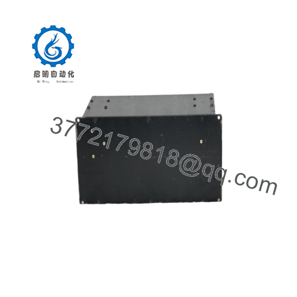
SE04-10WA
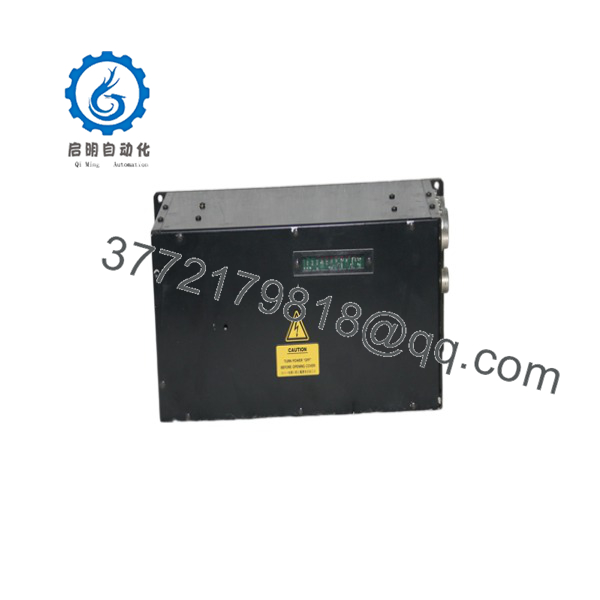
SE04-10WA
Installation & Configuration Guide
Stage 1: Pre-Installation
- Stop the machine through the approved production shutdown sequence and record all active alarms.
- Apply lock-out/tag-out to the incoming electrical supply. Verify absence of voltage with a properly rated meter before opening the electrical cabinet.
- Wear a grounded ESD wrist strap when handling control connectors, parameter boards, or interface wiring.
- Photograph the existing SE04-10WA from all sides before removal. Capture terminal markings, connector positions, cable labels, shielding terminations, grounding points, and any DIP-switch or jumper settings.
- Record the existing drive parameter set if the machine provides keypad, service-software, or controller-based parameter access. Save spindle speed limits, acceleration/deceleration settings, motor-current settings, fault-history data, and control-mode settings.
- Compare the replacement nameplate with the installed unit. Confirm model number, input rating, output rating, motor application, connector arrangement, and revision identification.
- Inspect the cabinet for heat damage, contamination, loose terminals, degraded fans, poor grounding, or unstable 24 V control power. Correct the root cause before installing the replacement drive.
Stage 2: Removal
- Confirm that all DC bus energy has discharged according to the machine manufacturer’s procedure. Do not assume the drive is safe immediately after power removal.
- Label every cable before disconnecting it, even if labels already exist. Legacy labels often differ from current drawings.
- Disconnect control connectors by their housings, not by pulling wires. Protect low-level analog, encoder, and communication wiring from static discharge and strain.
- Remove power and motor connections only after confirming terminal identification. Keep hardware organized to prevent mixing grounding or shielding hardware with power-terminal hardware.
- Support the SE04-10WA during removal. Use the specified mounting release method and avoid twisting the enclosure or applying force to terminals and connectors.
- Inspect mating connectors, pins, terminal blocks, and cable insulation. Replace damaged contact hardware before installing the new unit.
Stage 3: Installation
- Replicate every documented DIP-switch, jumper, rotary-address, and parameter setting exactly. Do not rely on a similar model’s default configuration.
- Mount the replacement SE04-10WA securely in the original location, maintaining the cabinet clearances and airflow direction required by the machine design.
- Reconnect grounding conductors first, then power wiring, motor wiring, control wiring, feedback wiring, and communication connectors.
- Torque power and ground terminals to the machine or drive documentation values. Do not estimate torque on high-current connections.
- Verify motor phase wiring and spindle rotation requirements before commanding production speed.
- Confirm that shields terminate exactly as on the original installation. Incorrect shield termination can introduce speed-command noise, encoder faults, or intermittent spindle alarms.
- Recheck all connectors and terminal screws. A loose control connector can produce erratic spindle enable, speed reference, or interlock behavior.
Stage 4: Power-On and Testing
- Before applying full machine power, test the relevant 24 V control rail and confirm there is no short circuit to ground.
- Apply power with the spindle mechanically safe and the process area clear. Observe drive LEDs or diagnostics for normal power and ready status; investigate any ERR, ALM, or fault indication before enabling the spindle.
- Confirm that the controller recognizes drive-ready, interlock, and fault-reset signals.
- Command a low-speed test first. Verify correct direction, stable speed feedback, motor current, vibration condition, and absence of abnormal noise.
- Test several controlled speed points before returning the saw to production. Compare actual spindle behavior against the old unit’s recorded parameters.
- If the drive interfaces with a machine controller, restore or download the approved logic and parameter backup only after confirming the target revision is compatible.
- Document the installed serial number, firmware/parameter revision, test results, installation date, and remaining buffer-stock quantity.
Firmware/Software Versions & Upgrade Notes
- Recommended firmware version: Install the same firmware and parameter revision as the removed -10WA whenever possible. Public listings do not provide a verified SINANO firmware revision matrix for this specific model, so the installed unit’s label, parameter backup, and machine OEM documentation are the controlling references.
- Parameter retention: Do not assume replacement hardware retains parameters. Treat the new unit as requiring a verified configuration clone unless the manufacturer’s service documentation explicitly confirms nonvolatile parameter transfer.
- Backward compatibility: A later hardware or firmware revision may accept the same model number but still differ in speed-reference scaling, fault-code behavior, communication timing, or spindle-enable logic.
- Forward compatibility: Do not install a later-revision -family drive solely because the connector fits. Confirm the exact I/O map, motor-control mode, acceleration profile, fault-reset behavior, and machine-controller interface.
- Upgrade warning: Avoid firmware upgrades during an emergency hardware swap. An upgrade can alter parameters or communication behavior, expanding a one-part replacement into a machine commissioning event.
- Downgrade warning: Do not downgrade firmware without a verified image and recovery method. A failed downgrade can leave a legacy drive non-operational and consume the only available spare.
- Control recommendation: Preserve three records with the on-site buffer stock: the removed drive’s nameplate photo, a complete parameter backup, and a documented functional-test record. This reduces lead time variability during a future failure event.
Frequently Asked Questions (FAQ)
Are these really new units?
Yes. This supply position is for New Original / New Surplus inventory only. A New Surplus unit is original OEM-manufactured inventory that has not been installed in production equipment. It should have zero wear on mounting surfaces, terminals, connectors, and backplane or interface contacts. Verify original packaging condition, serial number, nameplate photographs, QC documentation, and traceability records before release to site.
Why is New Surplus pricing lower than OEM new but higher than low-cost market alternatives?
OEM pricing reflects current manufacturer channels, support structures, and standard commercial terms. New Surplus pricing reflects the cost of locating, validating, storing, and preserving genuine legacy inventory after normal production support has declined. A low purchase price can conceal age-related capacitor degradation, relay wear, undocumented repairs, incorrect revisions, or altered firmware. For a discontinued spindle drive, the relevant comparison is total downtime exposure, not invoice price alone.
Is the SIN obsolete or EOL?
Market listings identify as discontinued, and available sources associate it with legacy DISCO saw equipment. Treat it as an EOL-risk spare until SINANO or the machine OEM confirms active production and support status.
For an active production machine, hold a minimum of one verified on-site unit. Hold two units when the line is high-value, the equipment cannot operate without the spindle, or qualified supply lead time is unpredictable.
Can be hot-swapped?
Do not hot-swap this drive unless the machine OEM’s service documentation explicitly authorizes that exact procedure. A spindle inverter contains energized power circuitry and interfaces with motor, control, safety, and interlock circuits. Removing or inserting it under power can damage the drive, controller, wiring, or spindle motor and can create a personnel hazard.
Will the replacement unit retain the original machine programming?
The machine PLC or CNC normally retains its own program, but the spindle inverter may contain independent motor and control parameters. Save the old drive’s settings before removal. Confirm speed-command scale, current limit, acceleration, deceleration, spindle enable logic, and fault-reset handling after installation.
What should be included in incoming quality verification?
Use an ESD-safe incoming inspection that includes serial-number and nameplate verification, packaging inspection, connector and terminal inspection, visual review for zero installation wear, insulation and ground-continuity checks where appropriate, controlled power-on testing, communication or handshake testing, and documented final inspector sign-off. Keep the report with the asset record so the unit can be deployed quickly during a future failure.
What warranty approach makes sense for this spare?
For a strategic legacy spare, specify a written 12 month warranty from the date of delivery or commissioning, subject to proper storage and installation conditions. Request documented acceptance criteria: correct model number, verified condition, functional power-on test, and compatibility confirmation against the original installed unit. Store the spare in ESD-safe, dry, temperature-controlled conditions and review it periodically as part of the lifecycle plan.



