
 WhatsApp: +86 16626708626
 Email:
  Phone: +86 16626708626
Description
Key Technical Specifications
| Parameter | Specification |
|---|---|
| Model | IES258 K |
| Full Configuration | IES258-5/1W..K |
| Brand | SINON |
| Manufacturer | Guangzhou Sinon |
| Product Type | Burner ignition controller |
| Primary Function | Automatic burner ignition and flame monitoring |
| Application | Industrial combustion equipment |
| Supply Voltage | 220–240 VAC* |
| Frequency | 50–60 Hz* |
| Installation | Industrial burner control panel |
| Typical System | Gas burner / furnace / kiln |
| Flame Control | Flame presence monitoring |
| Control Sequence | Ignition and burner safety sequence |
| Status / Fault Handling | Burner-control monitoring |
| Mounting / Enclosure | Verify against exact hardware revision |
*The 220–240 VAC and 50–60 Hz values are reported by secondary sources for the IES258-5/1W..K configuration. The available public documentation does not provide a sufficiently detailed OEM datasheet for every electrical and timing parameter, so these values should be confirmed against the installed unit’s nameplate before procurement.
A secondary technical listing gives additional values of 24 VDC supply, 0–5 VDC photoelectric input, 0–24 VDC switch output, <1 ms response time, -40 to +70 °C operating temperature, and 102 × 119 × 45 mm dimensions for an “IES258K controller module.” However, those specifications are not independently tied to the complete IES258-5/1W..K designation, so they should not be treated as confirmed specifications for this exact variant.
Product Introduction
The SINON IES258 K, commonly identified as IES258-5/1W..K, is an automatic burner ignition controller used in industrial combustion systems. Its role is to coordinate burner ignition and flame-monitoring functions so the combustion system can establish and supervise flame operation.
The controller is associated with industrial furnaces, kilns, and other gas-fired heating equipment. A documented project specification lists IES258 burner controllers together with SINON burners, gas valves, pressure-control equipment, and ignition transformers, confirming its use within integrated industrial combustion systems.
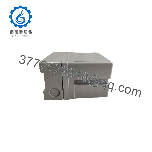
IES258 K
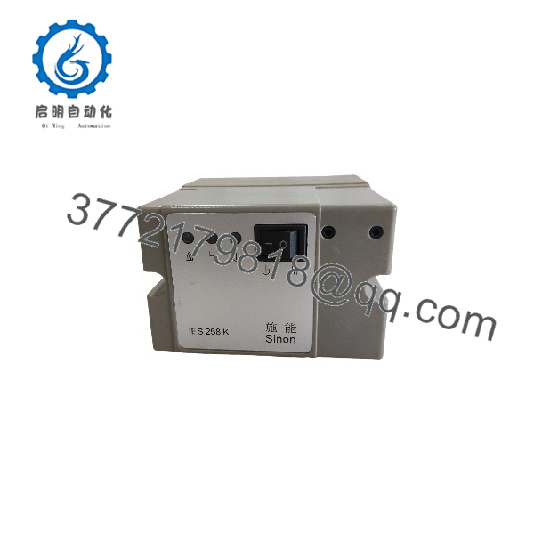
IES258 K
Installation & Configuration Guide
Stage 1 — Pre-Installation Preparation
- Record the complete controller designation from the existing nameplate, including IES258-5/1W..K and all suffix information.
- Verify the supply voltage and frequency before ordering a replacement.
- Document the existing wiring between the controller, burner, ignition transformer, flame sensor, gas valves, and safety interlocks.
- Back up or record the existing burner-control sequence where applicable.
- Shut down the combustion system using the plant’s approved burner shutdown procedure.
- Isolate electrical power and fuel supply before beginning replacement work.
⚠️ Estimated time: 20–40 minutes, excluding fuel-system isolation.
Stage 2 — Removing the Existing Controller
- Confirm that the burner is completely shut down.
- Isolate the controller’s electrical supply.
- Close and secure the relevant fuel supply according to the combustion-system procedure.
- Label every field wire before disconnecting it.
- Disconnect ignition, flame-monitoring, valve-control, interlock, and supply wiring.
- Remove the existing IES258 controller from its mounting arrangement.
- Inspect the wiring terminals for heat damage, corrosion, or loose connections.
⚠️ Do not bypass flame-safety interlocks to keep the burner operating during troubleshooting or replacement.
Stage 3 — Installing the IES258 K
- Verify the replacement nameplate against the original K / -5/1W..K configuration.
- Mount the controller securely in the burner-control enclosure.
- Reconnect the power supply using the original approved wiring arrangement.
- Reconnect the ignition and flame-monitoring circuits.
- Reconnect burner valve and safety-interlock circuits according to the applicable wiring diagram.
- Verify every terminal before energizing the controller.
- Check grounding and enclosure wiring.
- Confirm that no external jumper has been added to defeat a safety input.
⚠️ Burner controllers are safety-related combustion components. Terminal assignments must be taken from the correct SINON documentation for the exact variant.
Stage 4 — Power-On & Testing
- Restore electrical power without enabling the burner.
- Check the controller’s initial status.
- Verify all safety interlocks.
- Confirm the ignition transformer operates correctly during the commanded ignition sequence.
- Verify flame detection after ignition.
- Confirm the fuel valve sequence and flame-loss response.
- Perform a controlled burner start.
- Verify that loss of flame causes the required burner shutdown response.
- Check the complete sequence several times before returning the furnace or burner to automatic production operation.
⚠️ Estimated time: 30–60 minutes for functional testing, depending on the burner system.
FAQ
What is the SINON K?
It is an automatic burner ignition/control unit associated with SINON industrial burner systems. The more complete designation commonly found in listings is .
Where is the K used?
It is used in industrial combustion equipment such as furnaces, kilns, and gas-fired heating systems. A documented furnace project specifically lists burner controllers as part of its combustion system.
Is K the s /1W..K?
Available market documentation commonly uses as a shortened identification for . However, the complete nameplate should be checked because SINON combustion controllers can have configuration-specific suffixes.
What is the operating voltage?
A trade record identife -IW.K configuration as 220–240 VAC, 56–60 Hz, while another listing associae /1W..K with 220–240 VAC. Because public sources are inconsistent in their frequency notation, verify the exact nameplate before applying power.
Can I replace an K with another SINON controller?
Do not assume direct interchangeability. One secondary supplier specifically markets an SCU2.2-5/220 as a replacement for K, but replacement suitability depends on the burner, flame sensor, ignition transformer, valve sequence, safety circuit, and electrical configuration.
What should I verify before purchasing?
Verify the ce /1W..K designation, supply voltage, frequency, wiring configuration, flame-sensor arrangement, and physical condition. For a combustion-safety component, matching only the base model “ K” is not sufficient for a technically controlled replacement.



