
 WhatsApp: +86 16626708626
 Email:
  Phone: +86 16626708626
Description
Key Technical Specifications
| Parameter | Value |
|---|---|
| Manufacturer | SKF |
| Model Number | CMPT CTU |
| Common Product Name | Copperhead Transmitter Unit |
| Product Family | SKF Copperhead machinery fault-detection system |
| Product Type | Digital vibration and temperature transmitter |
| Vibration Channels | 1 |
| Temperature Channels | 1 |
| Primary Application | Continuous online fault detection for rotating machinery |
| Supported Machinery | Fans, pumps, motors, gearboxes, compressors, and similar rotating assets |
| Vibration Analysis Modes | SKF Acceleration Enveloping, acceleration, or velocity |
| Acceleration Enveloping Units | gE |
| Acceleration Units | g |
| Velocity Units | mm/s or in/s |
| Acceleration Frequency Range | 2 Hz to 20 kHz, RMS and peak-hold measurement |
| Velocity Frequency Range | ISO band, 10 Hz to 1 kHz |
| Low-Speed Capability | Bearing and gearbox monitoring down to 20 rpm; unbalance and misalignment monitoring down to 120 rpm with supported low-speed filtering and sensors |
| Vibration Output | 4–20 mA or 0–10 V DC proportional to selected full-scale vibration range |
| Temperature Output | 4–20 mA or 0–10 V DC proportional to selected temperature range |
| Digital Communications | CAN bus |
| Distributed Network Capacity | Up to 64 CMPT CTU units connected to one CMPT HMI/operator terminal |
| Alarm Communication Behavior | Unit initiates communication when an alarm occurs |
| Local Diagnostic Indicator | Front-panel SENSOR OK lamp: green for normal operation; red for sensor/CTU fault or vibration/temperature overload |
| Fault Analog Indication | Output below 4 mA or above 20 mA indicates a system fault |
| Sensor Compatibility | SKF CMPT sensor family and other compatible industrial accelerometers |
| Companion Display/Alarm Module | SKF CMPT DCL |
| Power-Protection Recommendation | Use a surge protector in the power connection as recommended by SKF |
| Replacement Requirement | Confirm exact CTU revision, sensor model, cable wiring, selected vibration mode, output range, power supply, CAN settings, and existing HMI/DCL configuration |
SKF identifies the CMPT CTU as a digital vibration and temperature transmitter used for 24/7 machinery fault detection. It analyzes one vibration and one temperature signal, supports Acceleration Enveloping, acceleration, or velocity modes, and provides proportional analog outputs plus CAN bus communication.
Product Introduction
SKF CMPT CTU, also called the Copperhead Transmitter Unit, is a digital vibration and temperature transmitter for continuous condition monitoring of rotating equipment. It processes one vibration channel and one temperature channel locally, then sends condition data to a PLC, DCS, SCADA system, SKF CMPT DCL alarm/display module, or CMPT HMI through analog outputs and CAN bus.
The unit supports SKF Acceleration Enveloping for bearing, gear, lubrication, and impact-related faults; standard acceleration for general vibration; and velocity for unbalance, misalignment, and looseness. It is a monitoring device, not a machine-protection trip module.
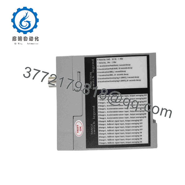
CMPT CTU
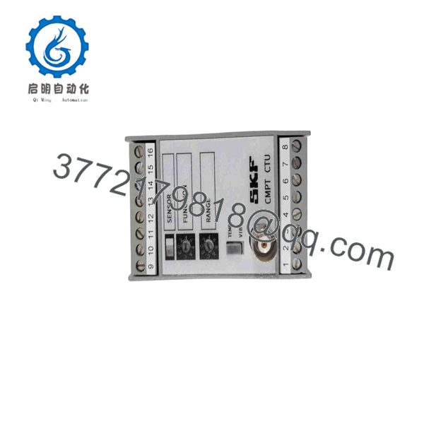
CMPT CTU
Troubleshooting Quick Reference
| Symptom | Possible Cause | Relevance to This Part | Quick Check Method | Recommendation |
|---|---|---|---|---|
| SENSOR OK lamp is off | Missing power, blown fuse, loose supply terminal, incorrect polarity, internal CTU failure | ✅ High | Measure the specified supply voltage at the CTU input terminals using a calibrated Fluke 115; check upstream fuse, common, and grounding | Verify supply voltage and polarity before replacing the CTU. Use surge protection on the supply as SKF recommends. |
| SENSOR OK lamp is red | Accelerometer or temperature sensor fault, cable open/short, sensor wiring error, vibration or temperature overload, CTU fault | ✅ High | Inspect sensor cable and connectors; measure sensor supply and continuity per sensor documentation; compare vibration/temperature to a portable reference instrument | A red lamp indicates a sensor/CTU fault or an overload condition. Diagnose the sensor and cable before replacing the CTU. |
| Analog output is below 4 mA or above 20 mA | System fault, sensor fault, CTU fault, open circuit, incorrect output wiring | ✅ High | Measure current in series with the affected output using a calibrated process meter; inspect CTU status lamp and sensor wiring | Treat out-of-range current as a fault indication, not a valid process value. SKF states that output below 4 mA or above 20 mA indicates a system fault. |
| PLC shows 0 mA or invalid vibration value | Open analog loop, no output supply/reference, wiring landed on wrong terminals, PLC input issue, CTU configuration mismatch | ✅ Medium | Measure current at the CTU output and again at the PLC/DCS input; compare wire numbers and common reference against the drawing | Repair the field loop or PLC input path before replacing the CTU. |
| Vibration value is consistently too high | Loose accelerometer mount, poor sensor coupling, damaged cable, incorrect selected range, wrong vibration mode, actual machine fault | ✅ Medium | Inspect sensor mounting torque and surface condition; compare with a portable vibration analyzer; confirm selected mode is gE, g, or velocity as intended | Correct mounting and configuration first. Do not suppress alarms until the machine condition is independently verified. |
| Vibration value remains near zero on a running machine | Open sensor circuit, wrong sensor type, incorrect cable, sensor installed on an isolated or low-energy point, failed CTU input | ✅ Medium | Check sensor connection, verify cable continuity, compare with a known-good sensor, and inspect the CTU red/green lamp | Verify the sensor and cable before declaring the CTU defective. |
| Temperature output is wrong or unstable | Temperature sensor open/short, incorrect sensor wiring, sensor placement issue, damaged cable, CTU configuration problem | ✅ Medium | Compare against a calibrated contact thermometer or process reference; check sensor wiring and continuity at the CTU terminal | Correct sensor or wiring problems first. Replace CTU only if the fault follows the transmitter with a verified sensor. |
| CAN bus communication fails | Incorrect CAN address, bitrate mismatch, reversed CAN_H/CAN_L, missing termination, damaged cable, HMI configuration error | ✅ High | Check CTU network wiring, node address, bitrate, shield connection, and termination; verify CMPT HMI diagnostics | Restore the existing CAN configuration. Do not assume a replacement transmitter has the same network settings. |
| Intermittent alarms during machine start or speed changes | Range too low, low-speed filter incorrectly selected, transient vibration, loose sensor connector, unstable supply | ✅ Medium | Trend CTU analog output and machine speed during startup; compare with portable analyzer data; inspect sensor cable strain relief | Review the selected range and measurement mode. Verify actual vibration before changing alarm limits. |
| Replacement CTU powers up but readings differ from old unit | Wrong output scaling, different selected vibration mode, sensor mismatch, CAN setup not restored, configuration not duplicated | ✅ High | Record old output at known machine condition; compare configured mode, range, decay setting, sensor type, and output type | Copy the approved configuration and validate against baseline data before returning the system to service. |
❗ Measurement-mode warning: Acceleration Enveloping, acceleration, and velocity do not measure the same fault behavior. Use Acceleration Enveloping for repetitive impacts from rolling bearing damage, gear faults, lubrication issues, or loose components. Use acceleration for overall high-frequency vibration and velocity for unbalance, misalignment, and looseness. Do not compare alarm limits from one mode directly with another.
❗ 4–20 mA fault warning: A current below 4 mA or above 20 mA is a fault indication, not a real vibration or temperature process value. Check the SENSOR OK lamp, cable, sensor, and loop wiring before adjusting scaling in the PLC.
❗ Sensor-mounting warning: A loose accelerometer can produce alarming data that looks exactly like a damaged bearing. Confirm the mounting surface, torque, thread condition, cable restraint, and sensor orientation before replacing electronics. I have seen a pump flagged for a bearing defect when the real problem was a sensor that had backed out one turn.
❗ Low-speed warning: Low-speed monitoring requires the correct sensor and filter arrangement. SKF describes bearing and gearbox monitoring down to 20 rpm and unbalance/misalignment monitoring down to 120 rpm under supported configurations. Do not apply normal-speed alarm settings to a slow-turning machine without reviewing the selected measurement method.
❗ CAN bus warning: Record network address, bitrate, wiring, termination, and CMPT HMI mapping before replacement. A unit can power up normally while remaining invisible to the monitoring system because it has a duplicate address or default network configuration.
❗ ESD and surge warning: Use a grounded wrist strap, keep sensor wiring isolated from high-voltage conductors, and install the power connection through surge protection as SKF recommends. A surge or static event can damage the CTU input without leaving visible marks.
Keep these checks in mind and you will save yourself 90% of typical rework time. If you need support, provide clear photos of the CTU label, SENSOR OK lamp state, terminal wiring, sensor model, sensor mounting point, measured analog output, CAN settings, CMPT HMI or DCL diagnostics, and recent vibration trends.
Frequently Asked Questions
What is the SKF CMPT CTU?
SKF CMPT CTU is a Copperhead digital vibration and temperature transmitter used for continuous machinery fault detection. It analyzes one vibration input and one temperature input, then sends proportional 4–20 mA or 0–10 V DC signals and CAN bus data to automation or SKF monitoring equipment.
It is commonly used on motors, pumps, fans, gearboxes, compressors, and other rotating machinery.
How many sensors does one CMPT CTU support?
Each CMPT CTU supports one vibration channel and one temperature channel. It can process signals from SKF CMPT sensors or other compatible industrial accelerometers.
For a multi-machine installation, SKF states that up to 64 distributed CMPT CTU units can connect to a single CMPT HMI/operator terminal.
What vibration measurements can the CMPT CTU perform?
The CTU supports three selectable vibration-analysis modes:
- SKF Acceleration Enveloping (gE): Identifies repetitive impact behavior associated with rolling bearing damage, gear faults, lubrication issues, and loose components
- Acceleration (g): Monitors overall machine and structural vibration
- Velocity (mm/s or in/s): Identifies unbalance, misalignment, and mechanical looseness
SKF specifies acceleration measurement from 2 Hz to 20 kHz and velocity over the ISO 10 Hz to 1 kHz band.
Does CMPT CTU provide 4–20 mA outputs?
Yes. The CMPT CTU provides analog outputs proportional to processed vibration and temperature, with 4–20 mA and 0–10 V DC output options. It also supports CAN bus communication.
Confirm the installed output type and scaling before replacement. A PLC analog input configured for 4–20 mA will not correctly interpret a 0–10 V CTU output, and a wrong vibration range will cause misleading engineering-unit values.
What does a red SENSOR OK lamp mean?
A red SENSOR OK lamp indicates a fault involving the sensor or CTU, or that vibration or temperature exceeds the configured range and creates an overload condition. Green indicates that the sensor connection and CTU operation are normal.
Start with the sensor cable, connector, supply, mounting, and actual machine condition. Do not assume the CTU is bad solely because the lamp is red.
Is CMPT CTU a machine-protection system?
No. The CMPT CTU is a machinery condition-monitoring and fault-detection transmitter. It provides condition data and alarms, but it should not be treated as a dedicated machinery-protection trip system unless the complete engineered system, safety analysis, alarm logic, final elements, and site procedures explicitly establish that function.
Do not bypass shutdown circuits or modify trip behavior based on a CTU reading without review by the responsible machinery and process-safety engineers.
Can I replace a CMPT CTU without copying its configuration?
You can physically mount it, but it may not produce comparable readings without restoring its configuration. Record the existing vibration mode, full-scale output range, acceleration-enveloping decay setting, sensor type, temperature setup, 4–20 mA or 0–10 V output choice, CAN node address, CAN bitrate, alarm mapping, and CMPT HMI/DCL settings before removal.
To be honest, configuration mismatch is the most common reason a new transmitter appears “wrong” after installation. The device may be working perfectly but measuring in velocity while the old unit used enveloped acceleration.
Why is a New Surplus CMPT CTU cheaper than current SKF supply?
New Surplus equipment can originate from unused maintenance spares, cancelled condition-monitoring projects, distributor overstock, machinery OEM inventory, or warehouse releases. Lower price can reflect legacy product status and secondary-market sourcing rather than an automatic defect.
Before issuing a purchase order, request:
- Actual photos of the CMPT CTU label, terminals, housing, and connectors
- Confirmation of New Original, New Surplus, Factory Sealed, or Refurbished (tested) condition
- Sensor and output interface confirmation
- CAN communication and configuration details, if available
- Evidence of no corrosion, heat damage, damaged terminals, altered labels, or rework marks
- Warranty duration, return terms, confirmed quantity, and dispatch lead time
What test process should a supplier complete before shipment?
A supplier should perform a documented, application-relevant test process:
- Inbound inspection and traceability: Verify full SKF identification labels, serial number or lot data where available, packing records, and source documentation. Inspect for corrosion, cracked housing, damaged terminals, contaminated connectors, altered labels, heat discoloration, and evidence of prior rework.
- Power and diagnostic test: Power the CTU from a protected regulated supply matching the unit’s requirement. Confirm normal startup, correct SENSOR OK indication with a known-good test sensor, stable current draw, and no abnormal heating.
- Vibration-input test: Connect a calibrated accelerometer simulator or compatible reference accelerometer. Test SKF Acceleration Enveloping, acceleration, and velocity modes at representative amplitudes and frequencies. Confirm that the analog output changes correctly through the selected range.
- Temperature-input test: Simulate or connect a compatible temperature sensor. Verify stable temperature output and correct fault indication for open or invalid sensor conditions.
- Analog-output test: Measure vibration and temperature outputs with a calibrated Fluke 789 process meter or equivalent. Confirm 4–20 mA and/or 0–10 V DC behavior, output scaling, and fault output outside the normal range.
- CAN communications test: Connect the unit to a known-good CAN test network and confirm address, bitrate, status, data exchange, and alarm-event communication. Verify that the unit can communicate with a representative CMPT HMI or diagnostic host when available.
- Load and thermal test: Run the transmitter with active vibration and temperature simulation for more than 24 hours where the test bench permits. Monitor output stability, CAN communication, diagnostic state, and temperature rise.
- Final QC and packaging: Require inspector sign-off, ESD-safe handling, terminal and connector protection, bubble wrap, heavy-duty corrugated boxing, and a dated QC-passed label. Test videos, photos, and the official test report should be available upon request.



