
 WhatsApp: +86 16626708626
 Email:
 Phone: +86 16626708626
Description
Core Product Summary
The SOCAPEL ST1 25-310 is a SOCASIN AC servo drive for three-phase servo motor applications in industrial motion-control systems. It operates from a 310 V DC bus and uses a 48 V DC auxiliary supply, with a documented switching frequency of 9.8 kHz.
The drive is identified in its user documentation as type ST1/25-310, part number 024.7751.B. It supports DC-bus interconnection between ST1 units and is documented for motor connections up to 100 m; longer distances up to 200 m are noted as possible but may introduce additional resolver reading inaccuracy. Correct mains supply, auxiliary supply, DC-bus arrangement, braking provision, and motor feedback wiring are central integration requirements.
Key Technical Specifications
| Parameter | Specification |
|---|---|
| Brand | SOCAPEL |
| Product family | SOCASIN AC servo drive |
| Exact type | ST1/25-310 |
| Part number | 024.7751.B |
| Product function | AC servo drive / servo amplifier |
| Mains supply | Three-phase mains with protective earth |
| DC bus | 310 V DC |
| DC-bus interconnection | Supported between ST1 units |
| Auxiliary supply | 48 V DC |
| Auxiliary-supply consumption | Maximum 0.8 A |
| Switching frequency | 9.8 kHz |
| Motor feedback | Resolver-based feedback |
| Documented motor cable length | Tested up to 100 m; up to 200 m possible with potential additional resolver reading inaccuracy |
| User manual | 024.8080.D |
Detailed Product Overview
The SOCAPEL ST1 25-310 is a SOCASIN-series AC servo drive intended to control a servo motor from a three-phase mains supply and a 310 V DC bus. In a motion-control architecture, it converts supplied electrical power into controlled three-phase output for the connected servo motor while using motor feedback for closed-loop position and speed control.
The 310 V DC bus is a defining integration characteristic. The ST1 documentation describes DC-bus interconnection between ST1 units, so system designers must account for bus configuration, protection, and the electrical relationship between drives sharing the same DC link. A dynamic braking resistor with protection is also identified in the drive’s documented supply arrangement.
The drive requires a separate 48 V DC auxiliary supply, with maximum consumption of 0.8 A. This supply is distinct from the three-phase mains input and must be included in cabinet power planning, wiring design, and protective-device selection.
The documented switching frequency is 9.8 kHz. This parameter affects the drive’s electrical operating behavior and should be considered alongside motor, cable, filtering, and installation requirements rather than treated as an isolated specification.
Motor feedback uses a resolver. The manufacturer documentation states that the distance between an ST1 unit and its motor has been tested up to 100 m. Distances up to 200 m are described as possible, but may produce additional resolver reading inaccuracy. Cable length, routing, shielding, and feedback-signal integrity therefore require attention during installation.
The product is documented as type ST1/25-310 with part number 024.7751.B in user manual 024.8080.D. When sourcing or replacing the unit, engineers should confirm both the type designation and the part number, as ST1 variants differ in rating and system configuration.
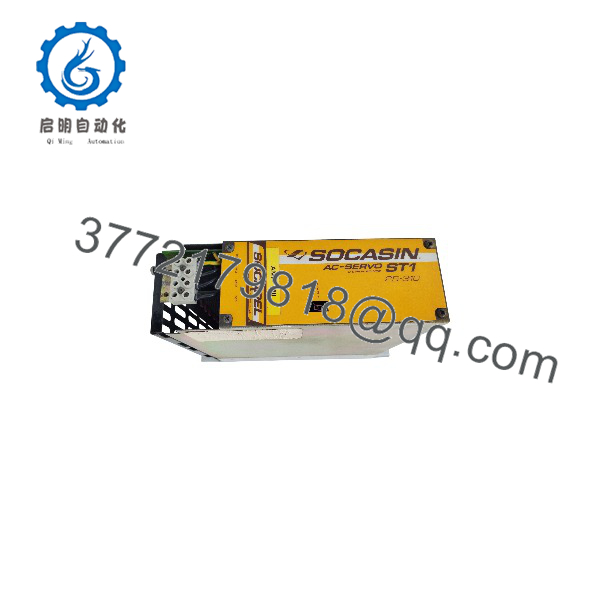
ST1 25-310
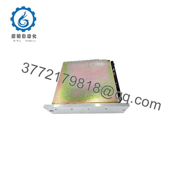
ST1 25-310
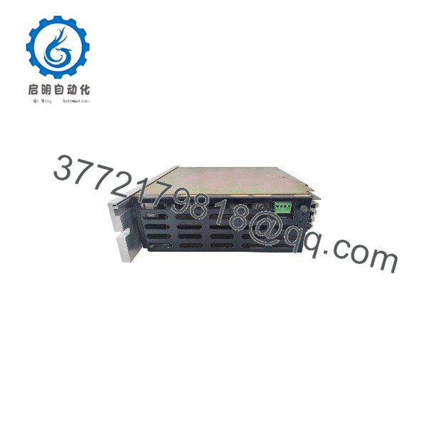
ST1 25-310
Dimensions, Mounting & Connection Notes
The documented connection arrangement includes a three-phase mains input with protective earth, a 310 V DC bus with interconnection capability between ST1 units, a 48 V DC auxiliary supply, and a resolver-connected servo motor. A dynamic braking resistor with protection is part of the documented supply arrangement.
The manufacturer documentation states that the distance between an ST1 unit and its motor has been tested up to 100 m. Distances up to 200 m are described as possible but may produce additional resolver reading inaccuracy.
Exact-model enclosure dimensions, mounting orientation, terminal torque values, wire-size limits, and clearance requirements are not available for publication.
System Compatibility & Integration Requirements
| Item / Dependency | Verified Compatibility or Requirement | Practical Note |
|---|---|---|
| Servo motor | AC servo motor with resolver feedback | The drive uses resolver-based motor feedback. |
| Mains supply | Three-phase mains with protective earth | The documented input arrangement includes 3L+PE. |
| DC bus | 310 V DC | The drive operates from a 310 V DC bus. |
| Multiple drives | DC-bus interconnection between ST1 units | Confirm bus topology, protection, and shared-bus electrical design. |
| Auxiliary supply | 48 V DC, maximum 0.8 A consumption | Provide a separate auxiliary supply in the control-system power design. |
| Braking | Dynamic braking resistor with protection | Include braking provision where the application requires it. |
| Motor cable | Tested up to 100 m; up to 200 m possible | Longer cable lengths may introduce additional resolver reading inaccuracy. |
| Documentation | User manual 024.8080.D | Use the model-specific manual for wiring, commissioning, and safety requirements. |
FAQ
What is the SOCAPEL ST1 25-310?
It is a SOCAPEL SOCASIN AC servo drive used to control a servo motor in an industrial motion-control system.
What is the exact product designation?
The drive is documented as type ST1/25-310, part number 024.7751.B.
What DC-bus voltage does it use?
It operates from a 310 V DC bus.
Can multiple ST1 drives share a DC bus?
Yes. The documentation describes DC-bus interconnection between ST1 units.
What auxiliary supply does the ST1 25-310 require?
It requires a 48 V DC auxiliary supply, with maximum consumption of 0.8 A.
What switching frequency does it use?
The documented switching frequency is 9.8 kHz.
What type of motor feedback does it support?
It uses resolver-based motor feedback.
How far can the motor be installed from the drive?
The distance between the ST1 unit and its motor has been tested up to 100 m; distances up to 200 m are described as possible but may introduce additional resolver reading inaccuracy.
Documented Performance Data
| Metric | Value/range | Test/operating condition |
|---|---|---|
| Switching frequency | 9.8 kHz | Documented drive operating parameter |
| Auxiliary-supply consumption | Maximum 0.8 A | 48 V DC auxiliary supply |
| Motor cable length | Up to 100 m tested; up to 200 m possible | ST1 unit to motor connection; longer distance may add resolver reading inaccuracy |



