
 WhatsApp: +86 16626708626
 Email:
  Phone: +86 16626708626
Description
Key Technical Specifications
- Manufacturer: Tokyo Electron Limited
- Manufacturer Part Number: 1381-648241-12
- Board Identification: TVB6003-1 / EIMC
- Product Type: Semiconductor equipment PCB assembly
- Product Category: Tool-specific electronic interface/control board
- Associated TEL Platforms: Public listings reference TEL Mark 7 and Mark 8 equipment; confirm the exact installed tool model before purchase
- Primary Function: Internal equipment interface and electronic control function; exact signal assignment is not publicly verified
- Installation Type: Internal electronics cabinet, controller enclosure, or tool-specific card location
- Board Revision: “-12” suffix must match the installed unit; also compare the TVB6003-1 and EIMC markings, connector population, and revision labels
- Communication Architecture: Not publicly verified; do not assume Ethernet, RS-232, RS-422, Profibus DP, DeviceNet, or any other protocol without the TEL electrical documentation
- Power Requirements: Not publicly verified; confirm supply rails, connector pinout, grounding, fuse protection, and test points from the applicable TEL schematic
- Firmware/Configuration: Record all programmable-device labels, board settings, jumpers, DIP switches, connector locations, and attached harness identification before replacement
- Handling Requirement: ESD-controlled handling, anti-static bagging, and clean board-level work practices required
- Lifecycle Status: Legacy TEL semiconductor-equipment spare; availability depends on surplus, used, or tested-refurbished inventory
Available market records identify 1381-648241-12 as a Tokyo Electron TVB6003-1/EIMC board. One used-equipment listing references installation and test use on TEL Mark equipment, including Mark 7 and Mark 8, while another lists the part as a used OEM board with limited stock. Public listings do not establish a complete OEM function, pinout, voltage, or tool-compatibility matrix.
Product Introduction
The Tokyo Electron 1381-648241-12, marked TVB6003-1/EIMC, is a tool-specific PCB Assembly used in compatible TEL semiconductor manufacturing equipment. Market references associate the board with TEL Mark 7 and Mark 8 platforms, where it supports an internal electronic interface or control role within the tool hardware.
This is an exact-number legacy replacement board, not a universal industrial interface card. Verify the full 1381-648241-12 label, TVB6003-1/EIMC marking, PCB revision, connector layout, and installed TEL tool model before ordering. A visually similar TEL board can have different backplane wiring, supply rails, firmware, or subsystem assignment.
Troubleshooting Quick Reference
| Symptom | Possible Cause | Relevance to this Part | Quick Check Method | Recommendation |
|---|---|---|---|---|
| Tool does not complete startup after maintenance | Loose board, missed connector, missing cabinet supply, safety interlock open, controller fault | ✅ Medium | Record the first alarm shown before resetting. Under approved shutdown conditions, inspect board seating, retainers, connectors, and associated cabinet fuses. Measure documented supply rails at the correct test points. | Check power, safety circuits, and connector seating before replacing the board. |
| EIMC-related or board-location diagnostic repeats | Internal logic fault, failed power rail, corrupted configuration, backplane/connector fault | ✅ High | Capture the diagnostic code and board location. Compare module LEDs or test points with a known-good cabinet section if available. Inspect board edge contacts and mating connectors with power removed. | Reseat the board first. Replace it only after confirming power, backplane, and controller communication are healthy. |
| One tool subsystem fails while other functions remain normal | Failed field device, cable or harness fault, I/O power loss, individual interface channel failure | ✅ Medium | Identify which harnesses and devices connect to the EIMC board. Trace the affected signal from the field device to the board connector using the TEL electrical drawing. | Do not condemn the PCB until field-device power, wiring, and interlocks are verified. |
| Multiple connected devices drop offline together | Common power issue, shared harness disconnect, board failure, cabinet connector problem | ✅ High | Check whether the failed devices share one EIMC connector or supply source. Inspect common returns, fuses, harness plugs, and cabinet terminal blocks. | A board failure is possible, but shared wiring and supply faults must be ruled out first. |
| Intermittent faults occur after cabinet vibration or door movement | Loose connector, damaged cable strain relief, oxidized contact, cracked solder joint, board defect | ✅ Medium | With the tool safely stopped, inspect connector locking, pin engagement, harness routing, and cable strain points. Review alarm timing relative to cabinet access or machine movement. | Repair harness and connector problems first. Replace the board if the fault follows the assembly after reseating. |
| Replacement board creates new alarms | Wrong revision, jumper mismatch, different connector layout, incompatible tool software or hardware configuration | ✅ High | Photograph the original board before removal. Match every label, revision code, connector, jumper, switch, and installed accessory against the replacement. | Stop commissioning if the behavior changes. Confirm exact compatibility using TEL documentation before further testing. |
| Board does not power up but other cabinet boards are healthy | Board supply fuse, local regulator failure, damaged backplane contact, PCB failure | ✅ Medium to high | Verify the documented input rail at the board connector and inspect edge contacts for damage or contamination. Do not probe unknown pins without the TEL schematic. | Replace the PCB only when a verified correct supply reaches the board but it remains nonfunctional. |
| Burn marks, corrosion, liquid residue, or damaged connector pins | Electrical overstress, contamination, moisture, ESD, external wiring short | ✅ High | Apply lockout/tagout and inspect both PCB sides, connectors, nearby harnesses, and power connections under magnification. Test associated field circuits for shorts before fitting another board. | Replace the damaged board and correct the external root cause before energizing the replacement. |
❗ Revision mismatch is a real risk: The 1381-648241-12 suffix and the TVB6003-1/EIMC board identification both matter. I have seen a technician install a close-looking TEL board, then lose a shift chasing a tool alarm caused by a revision mismatch rather than a wiring fault.
❗ Take photographs before removal: Photograph both board sides, labels, connectors, harness numbers, jumpers, DIP switches, and mounting location. Seriously. It is the fastest way to avoid reconnecting a legacy board incorrectly.
❗ Do not wire from memory: TEL equipment boards can use tool-specific connectors and mixed signal levels. A connector that physically fits is not proof that it belongs in that location. Use the current TEL electrical drawing.
❗ Verify power before ordering a board: A blown fuse, weak cabinet supply, failed interlock, or damaged backplane can mimic a failed PCB. Measure the approved supply test points under normal load before replacing hardware.
❗ Use ESD controls: Wear a grounded wrist strap and handle the PCB only by its edges. A static discharge can damage an interface input or logic device without leaving visible evidence.
Keep these checks in mind and you will save yourself 90% of typical rework time. If the fault remains unclear, contact technical support with high-resolution photos of the board labels and connectors, the TEL tool model, board location, exact alarm history, cabinet supply readings, and diagnostic logs.
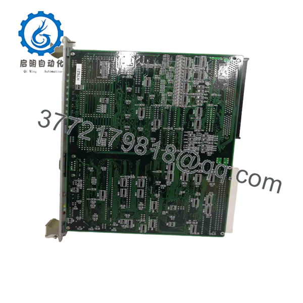
1381-648241-12
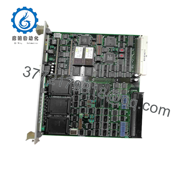
1381-648241-12
Frequently Asked Questions
What is TEL 1381-648241-12?
TEL 1381-648241-12 is a Tokyo Electron PCB Assembly identified in surplus-market records as . Available listings associate it with TEL Mark equipment, including Mark 7 and Mark 8 references, but the exact electrical role is not confirmed by a publicly available TEL OEM datasheet.
Is 1381-648241-12 compatible with every TEL Mark 7 or Mark 8 tool?
No. Public listings reference Mark 7 and Mark 8 equipment, but that does not establish universal compatibility across all tool variants, process modules, electrical revisions, or software configurations. Confirm the original board’s complete part number, /EIMC marking, revision code, connector layout, and TEL tool bill of materials before purchase.
Can I hot-swap this TEL board?
Do not hot-swap it unless the exact TEL service manual explicitly permits live replacement. Internal tool boards can carry logic, interface, control, and supply connections that are not designed for live insertion. Shut down the equipment under the approved maintenance procedure, apply lockout/tagout, verify stored energy is discharged, and use ESD precautions.
Will I lose recipes or process configuration when replacing it?
The main recipe database and process configuration typically reside in the tool controller, host system, or dedicated storage hardware rather than on every interface board. Still, do not assume the board has no configuration dependency. Record jumpers, DIP switches, programmable-device labels, connector positions, and board revision information. Save diagnostic logs and any service-software configuration available before removing the old unit.
How can I tell if the EIMC board is actually defective?
First verify cabinet power, fuses, safety interlocks, harnesses, backplane or carrier contacts, and connected field devices. The board becomes a likely cause when the correct power and valid incoming signals are present at the board boundary, but expected outputs, status, or communications fail through the board. A repeated location-specific diagnostic, visible component damage, or a fault that follows the board after controlled testing is stronger evidence.
Is 1381-648241-12 obsolete, and is stock limited?
Treat it as a legacy TEL semiconductor-equipment spare. Market listings show used boards and limited quantities; one seller listed two used units in stock, while other catalog listings may show out-of-stock status. Confirm the actual quantity, condition, board photographs, test scope, lead time, and warranty before issuing a purchase order.
Why can a surplus TEL board cost less than factory supply?
New Surplus inventory can come from unused maintenance stock, canceled fab projects, tool decommissioning, warehouse liquidation, or systems upgraded to newer platforms. A lower price is reasonable only when the supplier clearly states whether the item is New Original/New Surplus, used as removed, or Refurbished. Request full label photographs, board revision confirmation, condition details, test evidence, ESD-safe packaging confirmation, and warranty terms.
What testing should I request before purchase?
Request incoming inspection records, high-resolution images of both PCB sides, complete labels, connector faces, and any revision or programmable-device markings. Ask for verification that the board has no corrosion, damaged connectors, missing parts, heat discoloration, rework marks, or cracked components. If a compatible TEL Mark test rack is available, request power-on verification, board-status checks, interface-signal testing, and a dated test report. If the supplier cannot perform a live tool test, they should state that limitation clearly rather than claim full functionality.



