
 WhatsApp: +86 16626708626
 Email:
  Phone: +86 16626708626
Description
Key Technical Specifications
| Parameter | Specification |
| Manufacturer | Toshiba Corporation |
| Model Number | DI334 (Variant: DI334H) |
| System Compatibility | Toshiba PROSEC T3, T2, and V-Series Controller Racks |
| Number of Inputs | 16 channels (Hexadecimal labeled: 0-F) |
| Nominal Input Voltage | 12 VDC to 24 VDC |
| Operating Voltage Range | 9.6 VDC to 26.4 VDC |
| Input Current (Typical) | 4 mA per point at 12 VDC / 9 mA per point at 24 VDC |
| Isolation | Optocoupler isolation between field terminals and internal logic |
| Status Indicators | 16 red channel LEDs (High/Low bank display) + System Power status |
| Backplane Power Draw | 5 VDC, approx. 80 mA max internal bus consumption |
| Operating Temperature | 0°C to +55°C (32°F to 131°F) |
| Storage Temperature | -20°C to +75°C (-4°F to 167°F) |
| Unit Weight | 0.30 kg (0.66 lbs) |
Product Introduction
The Toshiba DI334 (also cataloged as DI334H) is a 16-channel digital input module engineered for legacy Toshiba PROSEC T3, T2, and V-Series programmable logic controller (PLC) racks. It converts binary signals from field switches, proximity sensors, relay contacts, and pushbuttons into 5 VDC logic signals readable by the central processor backplane. Built with industrial optocouplers, it insulates sensitive rack electronics from field electrical noise and voltage spikes.
Featuring individual LED diagnostic indicators for all 16 channels, the DI334 simplifies field signal verification for maintenance personnel. Sourcing a direct replacement DI334 unit restores discrete sensing channels on your existing Toshiba control rack immediately—avoiding expensive panel rewiring, software conversions, or full PLC platform overhauls.
Core Strategy 1: SOP Quality Transparency
To guarantee that obsolete Toshiba industrial stock operates reliably upon delivery, every DI334 card undergoes our 5-step bench verification process:
- Inbound Traceability & Visual Inspection
- Verification of original Toshiba factory serial tags, revision marks, and board silkscreens.
- Microscopic examination of backplane connector pins for corrosion, pin retraction, or bending.
- Visual audit for heat discoloration on internal resistor networks, cracked plastic latches, or damaged terminal strip rails.
- Live Functional Testing
- Mounted into a verified Toshiba PROSEC T-Series base rack powered by an authentic Toshiba power supply module.
- Power-On Self-Test (POST): Monitoring rack startup sequence to confirm backplane logic communication and LED bus status initialization.
- 16-Channel Signal Cycle Test: Exercised on an automated bench fixture cycling 12 VDC and 24 VDC inputs across all 16 channels continuously for 24 hours; signal filter timings and channel switching accuracy are logged.
- Generation of a formal bench test report documenting complete channel functionality.
- Electrical Parameter Testing
- Insulation Resistance: 500V Megger test between isolated field wiring terminals and the backplane logic ground plane (>10 MΩ rating).
- Backplane Power Rail Draw: Verified 5V DC bus current consumption using a Fluke 115 multimeter under full 16-channel active load.
- Hardware & Firmware Verification
- Check logic gate array chips and input filter RC networks.
- Verify hardware revision tags match OEM specifications for legacy T3/V-Series drop-in compatibility.
- Final QC & ESD Packaging
- Lead inspector sign-off on the quality control routing sheet.
- Module cleaned with non-conductive electronic cleaner and sealed inside a static-shielding ESD bag with desiccant.
- Packaged in custom anti-static foam inside a heavy-duty 200 lb test corrugated shipping carton.
Detailed bench test photos and channel diagnostic logs are available upon request prior to shipping.
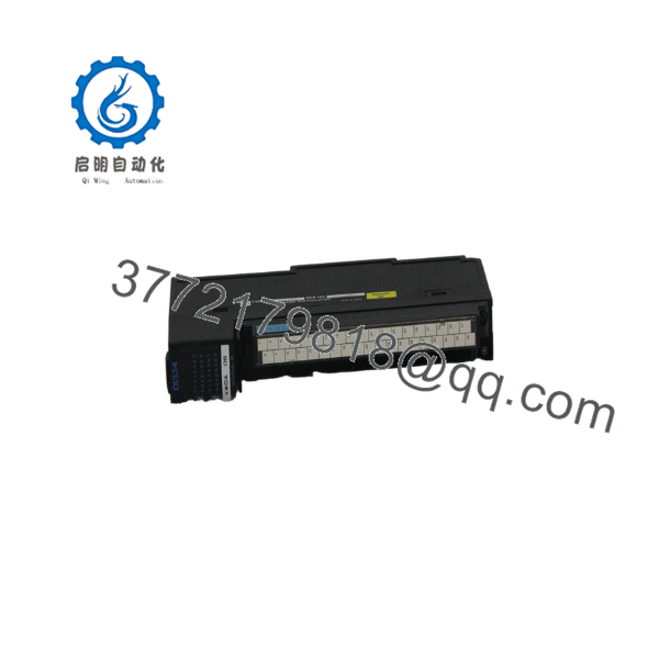
DI334
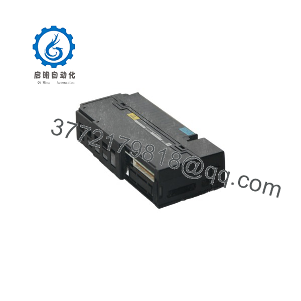
DI334
Troubleshooting Quick Reference
| Symptom | Possible Cause | Relevance to this Part | Quick Check Method | Recommendation |
| All channel LEDs off; module unread by CPU | Backplane 5V supply failure or blown internal logic fuse | 🟡 Medium | Measure 5V DC backplane power on adjacent rack slots using a multimeter. | If 5V backplane power is stable, the module’s internal power rail is dead. Replace module. |
| Field switch closed, but channel LED stays OFF | Blown channel optocoupler or burnt input resistor | ✅ High | Measure 12/24 VDC directly across the specific input terminal and common. | If 24 VDC is present at terminal screws but LED stays unlit, internal channel is dead. Replace card. |
| Bank of 8 inputs stops responding simultaneously | Blown group common wire or open group fuse trace | ❌ Low | Check continuity between field supply 0V/24V and the group common terminal. | Re-seat field wiring terminal arm and verify common connection before replacing module. |
| Channel LED flickers; CPU reads erratic input state | Degraded optoisolator or severe AC noise on field line | 🟡 Medium | Check input line with an oscilloscope for AC ripple (>2V) or ground floating. | If input voltage is clean DC but status chatters in CPU memory, replace the card. |
| System rack throws I/O bus error when module inserted | Damaged rear edge connector pins or bus buffer IC failure | ✅ High | Inspect rear pins for bends; install module into a known-good spare slot. | If fault follows the module to a clean slot, internal bus transceiver is fried. Replace card. |
If diagnostic testing is inconclusive, snapshot your rack status LEDs and consult our technical engineering team before pulling the module.
Core Strategy 2: Technical Pitfall & Survival Guide
Replacing a Toshiba PROSEC I/O module requires specific attention to hardware setup and wiring practices to avoid downtime.
- Field Common Sinking vs. Sourcing Setup
- The Trap: The 16 channels on the DI334 are organized in banks with shared common terminals. Mixing up positive (+24V) and ground (0V) common references between field devices will render an entire input bank dead.
- Avoidance: Label field harness commons clearly before removal. Verify whether your field devices (NPN vs PNP sensors) match the common polarity wired to the module.
- ❗ I’ve seen projects where a tech swapped a card and half the inputs failed to register, simply because a common jumper was landed on the wrong terminal. Check your panel schematics first.
- Terminal Connector Alignment Damage
- The Trap: Pressing the removable terminal block onto the module header at an angle can bend or push back the internal connector pins.
- Avoidance: Align the terminal strip square to the front guide slots. Apply even thumb pressure on both ends until the locking tabs snap firmly into position.
- ❗ Don’t force it. If the terminal strip doesn’t slide on smoothly, a pin is misaligned. Forcing it can destroy both the terminal strip and the internal header.
- Overvoltage on 24 VDC Field Lines
- The Trap: Unregulated cabinet power supplies putting out >28 VDC spikes can blow the input conditioning resistors or optocouplers on 16-point cards over time.
- Avoidance: Check DC voltage outputs on your cabinet power supply unit prior to reconnecting the field terminal arm to the replacement module.
- ❗ I once watched a tech complete a swap without checking power—the PSU was failing at 33V DC, which cooked the new card’s optocouplers instantly. Measure the voltage first.
- Electrostatic Discharge (ESD)
- The Trap: Touching exposed rear backplane gold fingers without dissipating body static charge can destroy sensitive CMOS logic ICs.
- Avoidance: Wear a grounded wrist strap attached to the cabinet ground frame before removing the card from its static bag.
- ❗ Handling a card in low-humidity weather without a strap can ruin internal logic before it’s even slotted into the rack. Always use an ESD wrist strap.
Follow these steps during replacement to avoid extended downtime and ensure a smooth system recovery.
Frequently Asked Questions (FAQ)
Is the Toshiba module hot-swappable?
No. Standard Toshiba PROSEC T3, T2, and V-Series racks do not support hot-swapping I/O modules. Inserting or removing the card while the rack power supply is active can cause high-current electrical transients across the backplane edge connector, damaging the logic interface on the module and adjacent cards. Always turn off rack power before replacing hardware.
What is the difference between model codes and DI334H?
and DI334H refer to the exact same functional 16-point digital input module architecture within Toshiba’s catalog. The H suffix typically designates a high-density or hardware revision update featuring improved optocoupler noise immunity. They are 100% pin-compatible and drop-in interchangeable.
Do I need to reconfigure PLC software when replacing this module?
No. If you are replacing a failed with an identical /DI334H unit, no software re-configuration or program modification is needed. The CPU reads the module’s I/O status based on its physical rack slot location automatically.
Why choose a New Surplus over upgrading the entire PLC system?
Replacing a legacy Toshiba PLC system requires re-engineering I/O racks, re-writing control code in modern software environments, rewiring panel layouts, and re-validating machine safety routines. Installing a New Surplus card restores production immediately at a fraction of the cost and time required for a complete control system migration.
Can the accept 12 VDC field inputs, or is it strictly 24 VDC?
The input circuit is wide-range rated to operate on both 12 VDC and 24 VDC nominal field logic levels (operating range 9.6 VDC to 26.4 VDC). It automatically registers valid ON signals above 9.6 VDC without requiring physical jumper modifications.



