
 WhatsApp: +86 16626708626
 Email:
  Phone: +86 16626708626
Description
Key Technical Specifications
| Parameter | Specification |
|---|---|
| Manufacturer | TRICONEX / Schneider Electric |
| Model | 2301 |
| Product Type | Digital Input Baseplate |
| System | Trident |
| I/O Function | Digital Input |
| Number of Points | 32 |
| Compatible Module | Model 3301 DI Module |
| Field Supply | +24 V DC, redundant supply inputs |
| Field Connections | 32 digital input channels |
| Architecture | Triple-redundant Trident I/O |
| Typical Fault Current | 130 mA |
| Maximum Fault Current | 200 mA |
| ADC Scan Time | <1 ms for all 32 points |
| Field Input Wiring | Dual field-power arrangement |
| Mechanical Interface | Trident I/O module/baseplate |
| Application | Safety instrumented systems and critical process control |
The Trident Planning and Installation Guide identifies Model 2301 specifically as the Digital Input Baseplate and shows 32 field-input points with redundant field-power connections. The same documentation specifies a typical field short-to-ground fault current of 130 mA and a maximum of 200 mA.
The Triconex architecture uses triple-modular redundancy for safety and critical-control applications. Schneider Electric describes Triconex as a TMR safety-system architecture, while its current product documentation is presented under the EcoStruxure Triconex name.
Product Introduction
The TRICONEX 2301 is a Trident 32-point digital input baseplate used with the Model 3301 digital input module. It provides the physical field interface for digital input signals and connects the field wiring to the Trident I/O architecture. The documented design includes redundant field-power connections and 32 input channels.
Do not confuse the 2301 with a digital input module itself. Model 2301 is the baseplate; Model 3301 is the associated digital input module. That distinction matters when ordering a replacement because a 2301 alone does not perform the input processing function.
Installation & Configuration Guide
Stage 1: Pre-Installation Preparation — 10–15 Minutes
⚠️ Safety First: A Triconex/Trident installation can form part of a safety instrumented function. Place the affected SIF and process in the approved maintenance state before disconnecting field wiring. Follow the site’s LOTO, bypass-management, and functional-safety procedures.
Tools Required:
- ESD wrist strap
- Digital multimeter
- Appropriate screwdriver
- Wire labels
- Smartphone/camera
- Triconex/Trident maintenance documentation
Data Backup:
- Record the exact 2301 model number.
- Record the installed 3301 DI module.
- Photograph all 32 field connections.
- Record both field-power connections.
- Document channel assignments.
- Photograph the baseplate and adjacent I/O modules.
- Record the Trident I/O configuration.
- Verify whether the installation uses a redundant field-supply arrangement.
⚠️ Critical: Do not substitute a different Triconex baseplate solely because it physically fits. Triconex documentation differentiates standard digital-input baseplates from high-voltage and other I/O configurations.
Stage 2: Removing the Old Baseplate — 10–15 Minutes
- Place the process in its approved maintenance state.
- Apply the required LOTO and safety-system bypass procedures.
- Verify field power is isolated where required.
- Label every field conductor.
- Photograph the terminal arrangement.
- Record all 32 channel assignments.
- Disconnect the field wiring carefully.
- Disconnect the associated 3301 module according to the Trident maintenance procedure.
- Release the baseplate from its mounting arrangement.
- Remove the 2301 without stressing adjacent I/O connections.
- Inspect the replacement interface for bent contacts, corrosion, or contamination.
- Retain the original baseplate until commissioning is complete.
Stage 3: Installing the New Baseplate — 10–15 Minutes
- Verify the replacement is TRICONEX 2301.
- Verify the associated I/O module is Model 3301.
- Inspect the mechanical and electrical interfaces.
- Mount the 2301 in the correct Trident position.
- Verify mechanical locking.
- Reinstall the 3301 digital input module.
- Reconnect all 32 field-input circuits.
- Reconnect the redundant field-power connections.
- Verify polarity and terminal assignments.
- Check every conductor against the original wiring photograph and approved drawing.
Self-Checklist:
- 2301 baseplate verified
- 3301 module verified
- 32 channels documented
- Field-power wiring checked
- Polarity checked
- Mechanical locking secured
- All terminals tightened
- Adjacent I/O connections undisturbed
Stage 4: Power-On & Testing — 20–40 Minutes
- Perform a complete wiring inspection.
- Verify field-power voltage.
- Restore power according to the approved Trident maintenance procedure.
- Confirm the 3301 module is correctly recognized.
- Check system diagnostics.
- Verify all expected input channels.
- Test representative field contacts.
- Verify ON/OFF status at the Trident controller.
- Confirm channel diagnostics remain normal.
- Perform the required proof-test or loop-check procedure.
- Remove the approved bypass only after the SIF has passed its required checks.
- Return the system to normal operation.
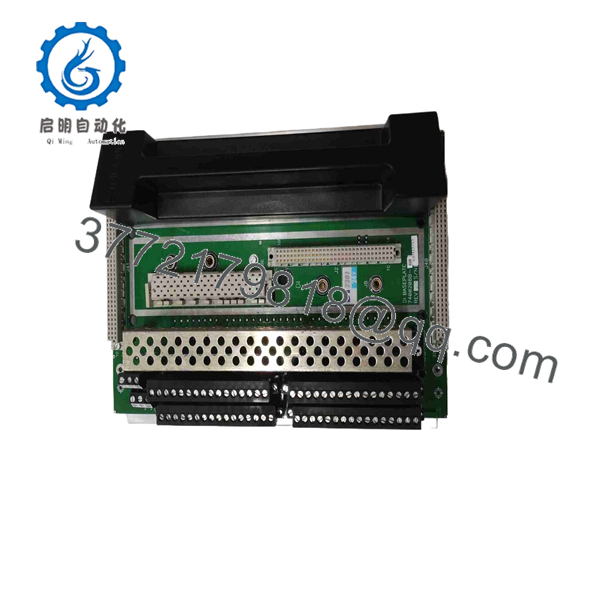
2301
Common Replacement Pitfalls
❗ 1. Confusing the Baseplate With the I/O Module
The most important identification issue is simple: 2301 = digital input baseplate; 3301 = digital input module. Ordering a 2301 when the failed component is actually a 3301 will not solve the problem.
❗ 2. Assuming Every Triconex DI Baseplate Is Equivalent
Triconex uses different baseplate arrangements for different I/O types and applications. The published Trident documentation identifies the 2301 for typical Model 3301 digital-input applications and separately lists high-voltage and hazardous-location termination options.
❗ 3. Losing the Channel Map
There are 32 input points. Label every conductor before removal. A single channel moved to the wrong terminal can create a logic-level problem that looks like a failed field device.
❗ 4. Ignoring Redundant Field Power
The 2301 field-connection documentation shows separate field-power paths. Check both supply paths rather than verifying only one voltage measurement.
❗ 5. Treating a Safety-System Replacement Like Ordinary PLC Maintenance
A baseplate replacement can affect a safety instrumented function even when the actual logic program remains unchanged. Follow the site’s approved bypass, proof-test, and return-to-service procedure.
Frequently Asked Questions (FAQ)
1. What is the TRICONEX 2301?
The TRICONEX 2301 is a Trident Digital Input Baseplate. It provides the field-wiring interface for a Model 3301 32-point digital input module.
2. Is the 2301 the same as the 3301?
No. The 2301 is the baseplate, while 3301 is the digital input module installed on that baseplate. They are separate hardware components and should be ordered separately when necessary.
3. How many digital inputs does the 2301 support?
The Trident documentation specifies 32 digital input points for the Model 2301 baseplate.
4. What voltage does the TRICONEX 2301 use?
The documented field connection shows +24 V field power, with redundant field-power connections. The exact field-device voltage and wiring must be verified against the installed Model 3301 configuration and site drawings.
5. Can the 2301 be replaced online?
Triconex systems support online module replacement in appropriate architectures, and Schneider Electric describes online I/O replacement as a feature of Triconex systems. However, baseplate replacement is not something I would treat as automatically hot-swappable. Follow the specific Trident maintenance procedure and site safety authorization for the installed hardware.
6. Is the TRICONEX 2301 obsolete?
The 2301 belongs to the legacy Trident hardware family. Schneider Electric’s current Triconex portfolio is presented under EcoStruxure Triconex, including newer safety-system platforms. Existing Trident installations remain in service, so actual spare-parts availability depends on the exact hardware and supplier inventory.
7. What should I verify before purchasing a surplus 2301?
Verify the exact 2301 model, Trident compatibility, associated 3301 module, physical condition, terminal condition, and test status. For a safety-system spare, also request photographs of the actual unit and confirmation that the baseplate has been inspected for damaged contacts and terminal hardware. Do not accept a generic listing described only as a “Triconex controller module”; the documented function of the 2301 is specifically the digital input baseplate.



