
 WhatsApp: +86 16626708626
 Email:
  Phone: +86 16626708626
Description
Key Technical Specifications
| Parameter | Value |
|---|---|
| Model | Triconex 8111 |
| Product type | High-density Tricon expansion chassis |
| Primary role | Adds I/O and communication capacity to a Tricon system |
| Compatible system | Tricon safety instrumented system |
| Chassis configuration | High-density expansion chassis |
| Physical module locations | 30 physical slots |
| Logical module positions | Eight logical module slots with TMR or hot-spare arrangements |
| Installed power locations | Two redundant power-module positions |
| Power-module compatibility | 8310, 8311, or 8312 power modules, application dependent |
| Typical power-module output | 175 W at 60 °C ambient |
| Logic-power output | 6.5 VDC ±1% |
| Maximum logic-power current | 27 A at 60 °C ambient |
| Recommended incoming power | Minimum 240 W per installed power module |
| I/O expansion interface | Two triplicated RS-485 I/O bus port sets, channels A, B, and C |
| I/O bus communication rate | 375 kbit/s between I/O modules and main processors |
| Communication-module interface rate | 2 Mbit/s |
| Maximum main-to-final expansion I/O bus length | 100 ft / 30 m |
| Communication-module restriction | Communication modules permitted only in Expansion Chassis 2 |
| Rack installation | 19-inch rack-mount chassis |
| Chassis dimensions | 19 × 22.75 × 17.75 in. |
| Chassis dimensions | 48.3 × 57.8 × 45.1 cm |
| Approximate chassis weight | 54 lb / 24.5 kg, excluding modules |
| Construction | Black zinc-plated, welded cold-rolled steel |
| Product status | Discontinued / legacy safety-system chassis |
The Triconex 8111 is the high-density expansion chassis used to add I/O and eligible communication modules to a Tricon safety system. It uses two redundant power-module positions and triplicated RS-485 expansion-bus paths. The total I/O bus cable distance from the 8110 main chassis to the final expansion chassis must not exceed 100 ft (30 m).
Product Introduction
The Triconex 8111 is a high-density expansion chassis for the Tricon safety instrumented system. It extends a Tricon main chassis by providing physical locations for additional TMR I/O modules, hot-spare pairs, and approved communication modules in safety-critical applications such as emergency shutdown, burner management, turbine protection, fire and gas, and process shutdown systems.
The 8111 chassis uses two redundant power modules and triplicated RS-485 I/O expansion connections. It provides 30 physical slots arranged into eight logical positions, where a logical slot may hold a TMR module set or a primary/hot-spare module arrangement. Communication modules are restricted to Expansion Chassis 2, not every 8111 in a multi-chassis system.
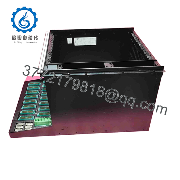
8111
Troubleshooting Quick Reference
| Symptom | Possible Cause | Relevance to this Part | Quick Check Method | Recommendation |
|---|---|---|---|---|
| Entire 8111 chassis is offline | Missing incoming power, both power modules faulted, loose backplane connection, I/O bus disconnection | ⚠️ Medium | Check input voltage and protective devices feeding both installed power modules. Review power-module alarm contacts and front-panel indicators. Inspect the triplicated I/O bus connections. | Start with incoming power and bus wiring. Do not replace the chassis until both power modules and external feeds are verified. |
| One power module alarm is active | Single power-feed loss, power-module failure, missing module, overload, poor module seating | ❌ Low | Check the affected power module’s AC/DC input, alarm contact, and seating. Confirm the redundant supply still carries the chassis load. | Replace or repair the individual power module, not the chassis, if the backplane and second supply remain normal. |
| Both power modules report alarms | Common input-power loss, overloaded chassis, shared wiring fault, incorrect power-module type | ⚠️ Medium | Measure each incoming feed under load. Review chassis module loading and confirm the installed 8310, 8311, or 8312 modules match the system voltage and hazardous-area requirements. | Correct the common feed or loading issue first. A simultaneous dual-power alarm does not automatically mean the 8111 backplane has failed. |
| I/O modules in the chassis show communication faults | Open or miswired I/O bus path, wrong chassis order, excessive total cable length, damaged bus connector | ✅ High | Inspect both triplicated RS-485 I/O bus port sets for channels A, B, and C. Compare chassis order and bus routing to the approved Tricon drawings. Measure or confirm total main-to-final chassis distance is 100 ft / 30 m or less. | Check bus cables, connector seating, and chassis sequencing before replacing the chassis. A single open A/B/C path can create partial diagnostics without a failed backplane. |
| Only one TMR leg reports a fault | One module leg fault, one bus-channel issue, connector contamination, backplane contact issue | ⚠️ Medium | Review the TriStation diagnostics to identify whether the fault follows a module leg, a bus channel, or a chassis location. Reseat only under an approved online-maintenance procedure. | Swap only with approved, like-for-like spare modules. If the fault stays with one physical chassis position across known-good modules, inspect the backplane and use qualified service support. |
| Multiple adjacent module positions fail | Backplane damage, chassis contamination, missing power rail, loose module retention hardware | ✅ High | Compare fault location against the chassis slot map. Inspect power module outputs, connector contacts, and mechanical seating with power isolated if required by the maintenance procedure. | Treat adjacent-position faults seriously. Do not continue swapping safety modules casually; preserve diagnostics and involve the site SIS authority. |
| New module is not recognized | Incorrect module type, unsupported system revision, incorrect slot assignment, bent connector pins | ⚠️ Medium | Confirm module part number, Tricon system revision, slot location, and hot-spare pairing. Inspect module and chassis connectors for bent, recessed, or contaminated contacts. | Never force a module into the 8111. Confirm approved module-to-slot compatibility and use the plant’s change-control procedure. |
| Communication module is not detected | Installed in the wrong expansion chassis, configuration mismatch, module fault | ⚠️ Medium | Verify whether the 8111 is configured as Expansion Chassis 2. Confirm the communication module’s slot assignment and TriStation configuration. | Communication modules can only be installed in Expansion Chassis 2. Move or configure only through approved SIS engineering control. |
| System fault appears after adding an expansion chassis | Incorrect chassis ID/order, bus cable misrouting, power modules not energized, configuration not updated | ✅ High | Compare physical chassis order, bus cable routing, and installed modules to the released engineering drawings. Review the TriStation project and system diagnostics before download. | Stop and reconcile the physical installation with the approved project. Do not make live edits to a safety system simply to clear diagnostics. |
| Chassis or modules run hot | Cabinet cooling failure, excessive module loading, blocked airflow, ambient temperature too high | ⚠️ Medium | Measure cabinet air temperature near the chassis and inspect cooling fans, filters, and clearances. Confirm the power loading is within the installed supply capacity. | Correct cabinet cooling and power loading. The power modules are rated at 175 W at 60 °C; high cabinet temperature reduces available margin. |
| System loses several chassis after maintenance | Common main-chassis issue, primary bus cable disturbed, controller fault, power-distribution outage | ❌ Low | Determine whether the main chassis and other expansion chassis are also affected. Inspect the first I/O bus connection and common cabinet supplies. | A multi-chassis event usually points upstream. Start at the main chassis, primary I/O bus, and shared power distribution. |
❗ Safety-system warning: The Triconex 8111 belongs to a safety instrumented system. Do not treat it like ordinary PLC rack hardware. Any chassis replacement, module relocation, power-module change, communication change, or TriStation configuration download must follow the site’s SIS management-of-change process, approved cause-and-effect documentation, proof-test requirements, and applicable functional-safety procedure.
❗ I/O bus warning: The 8111 depends on triplicated RS-485 I/O bus paths. Document the A, B, and C cable routing before removal. Do not cross-connect channels or assume that similar connectors can be reattached in any order. A single channel issue can remain masked by TMR diagnostics until another failure occurs.
❗ Power-module warning: The chassis requires two correct power modules for redundant operation. Available Tricon documentation lists 8310 for 120 VAC/VDC, 8311 for 24 VDC, and 8312 for 230 VAC applications. For ATEX-required installations, do not use the 8312 power module; verify the approved 24 VDC 8311 supply architecture from the applicable system documentation.
❗ Slot-assignment warning: Take high-resolution photos of every installed module, termination panel, cable, chassis label, and bus connection before moving equipment. Record the released TriStation configuration and chassis order. An 8111 chassis can physically accept many modules, but that does not make every physical slot or expansion-chassis position valid for a given application.
Keep these checks in mind and you will save yourself 90% of typical rework time. If diagnostics remain unresolved, contact qualified Triconex technical support or the plant’s SIS engineer with the chassis serial number, power-module models, TriStation diagnostic export, module location chart, I/O bus cable photos, and cabinet power measurements.
Frequently Asked Questions (FAQ)
Q: What is the Triconex 8111?
A: The Triconex 8111 is a high-density expansion chassis for a Tricon safety instrumented system. It does not execute the main safety application by itself. Instead, it expands the system by housing additional I/O modules and, when it is designated as Expansion Chassis 2, approved communication modules.
Q: How many modules can an 8111 chassis hold?
A: The 8111 has 30 physical module slots arranged as eight logical module positions. In a TMR installation, each logical position can use three physical module locations. In a hot-spare arrangement, a primary module and a matching spare use two locations. The exact usable arrangement depends on the released system design and installed module types.
Q: Does the Triconex 8111 include power supplies?
A: The chassis includes two positions for redundant Tricon power modules, but the installed power-module models must be confirmed from the actual unit and system design. Tricon documentation identifies compatible 8310, 8311, and 8312 modules for 120 VAC/VDC, 24 VDC, and 230 VAC input applications, respectively. Do not assume the chassis listing includes those modules unless the seller confirms it in writing.
Q: Can I install a communication module in any 8111 expansion chassis?
A: No. Communication modules can only be installed in Expansion Chassis 2. If your system contains multiple 8111 chassis, confirm the physical and configured chassis order before installing or moving a communication module. This is a common commissioning trap because the module can physically fit while remaining invalid in the system architecture.
Q: What is the maximum cable length between the main chassis and expansion chassis?
A: The combined I/O bus distance from the 8110 main chassis to the last expansion chassis must not exceed 100 ft, or 30 m. Include every segment of the routed I/O bus cable in the calculation, not just the straight-line cabinet distance. Excessive length or incorrect A/B/C bus routing can create intermittent or persistent I/O communication faults.
Q: Is the 8111 hot-swappable?
A: No. The chassis itself is not a hot-swappable component. Individual Tricon modules may support online replacement under tightly controlled site procedures, but removing or replacing an entire 8111 chassis requires a planned outage or an engineered migration strategy. Never disconnect chassis power or I/O bus connections during live safety-system operation without approved SIS authority and a documented bypass strategy.
Q: Is the Triconex 8111 obsolete?
A: Yes. The 8111 is legacy Tricon hardware and has been identified by aftermarket sources as discontinued by the manufacturer. It remains in service at many installed sites, so new surplus, tested used, and refurbished inventory may be available, but availability, power-module inclusion, backplane condition, and documentation vary by supplier.
Q: Why is New Surplus 8111 stock less expensive than current safety-system hardware?
A: New Surplus generally refers to unused original stock from plant spares, canceled projects, equipment liquidation, or discontinued inventory. It can cost less because it may not include current factory support, certification records, software compatibility assurance, installed power modules, or factory warranty coverage. Before purchase, request photos of the exact chassis, serial label, backplane connectors, installed power-module slots, slot blanks, damage inspection, functional-test method, written warranty, and actual delivery lead time.



