
 WhatsApp: +86 16626708626
 Email:
  Phone: +86 16626708626
Description
Key Technical Specifications
| Parameter | Value |
|---|---|
| Model | 9000-025 |
| Brand | Triconex |
| Product Family | Tricon TMR |
| Product Type | TriBus communication cable assembly |
| Application | Inter-chassis communication |
| Cable Length | 2.5 m, according to available supplier documentation |
| Connector | D-sub, 37-pin male, according to available supplier documentation |
| Communication Interface | Proprietary Tricon TriBus |
| Architecture | Triple Modular Redundancy (TMR) |
| Installation | Tricon safety-system chassis/cabinet |
| Typical Use | SIS, ESD, F&G and other safety-control applications |
| Condition | Confirm exact physical condition and packaging with supplier |
Technical verification note: The 2.5 m length, 37-pin connector specification, and detailed electrical characteristics above come from supplier-published information rather than an OEM datasheet located during this search. They should therefore be checked against the identification label and OEM documentation before a safety-system replacement.
Product Introduction
The Triconex 9000-025 is identified in available industrial automation listings as a Tricon/Triconex TMR system communication component, with detailed listings describing it as a pre-terminated TriBus inter-chassis cable assembly. Its purpose is to establish the communication link between Tricon chassis within a safety instrumented system.
For replacement work, the important point is not simply the part-number match. Verify the connector arrangement, cable length, chassis interfaces, system revision, and physical condition before installation. Triconex documentation should take precedence over reseller specifications where the two differ.
Installation & Configuration Guide
Stage 1: Pre-Installation Preparation — About 5–10 Minutes
⚠️ Safety First: Put the SIS/control system into the approved maintenance state. Follow the site’s safety procedure and OEM shutdown requirements before disconnecting the cable. Do not assume that a communication cable can be removed under power.
Tools Required:
- ESD wrist strap
- Appropriate screwdriver
- Multimeter
- Cable labels
- Smartphone or camera for configuration records
Data Backup:
- Record the exact existing part number.
- Photograph both connector ends before removal.
- Photograph cable routing and shield/ground connections.
- Record the chassis and rack positions connected by the cable.
- Keep the removed cable until the replacement has passed commissioning.
Stage 2: Removing the Old Cable — About 5 Minutes
- Confirm the approved shutdown state.
- Do not pull on the cable itself.
- Release the connector locking hardware.
- Disconnect each end straight from its chassis interface.
- Inspect the connectors for bent contacts, contamination, corrosion, or mechanical damage.
- Inspect the chassis mating interfaces before installing the replacement.
⚠️ Important: Do not force a connector that does not align naturally. A damaged TriBus interface can create a much larger outage than the original cable failure.
Stage 3: Installing the New 9000-025 — About 5–10 Minutes
- Verify the complete part number: 9000-025.
- Compare the replacement against the removed cable before installation.
- Confirm connector type and physical termination.
- Route the cable along the original path.
- Keep the cable away from high-current power wiring where practical.
- Insert each connector carefully and evenly.
- Secure the connector locking hardware.
- Confirm that neither connector is under mechanical tension.
Self-Checklist:
- Correct 9000-025 part number
- Connector type verified
- Cable routing reproduced
- Connectors fully seated
- Locking hardware secured
- Cable not sharply bent or mechanically loaded
- Shield/ground arrangement reproduced
Stage 4: Power-On & Testing — About 10–15 Minutes
- Perform a final visual inspection before energizing the system.
- Verify there are no loose conductors, damaged connectors, or trapped cables.
- Restore power according to the site’s approved procedure.
- Check the Tricon system diagnostics.
- Confirm communication between the affected chassis.
- Check for communication or chassis diagnostic alarms.
- Verify the expected controller/I/O status.
- Run the site’s approved functional test before returning the SIS to service.
⚠️ Troubleshooting Note: If the replacement does not establish communication, do not immediately assume that the cable is defective. Check connector seating, chassis addressing/configuration, cable routing, mating-interface condition, and system diagnostics first.
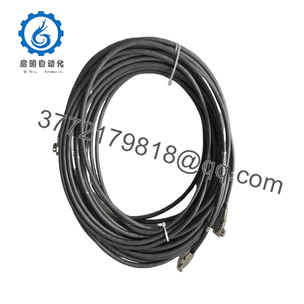
9000-025
Frequently Asked Questions (FAQ)
Q1: What is the Triconex 9000-025?
Available industrial listings identify it with the Tricon/Triconex TMR safety platform. One detailed listing specifically identifies 9000-025 as a TriBus inter-chassis communication cable assembly.
Q2: Is 9000-025 a CPU or I/O module?
The available sources are inconsistent. One supplier categorizes it as a safety-system module, while another provides detailed specifications for a pre-terminated TriBus cable assembly. For procurement, verify the physical part and OEM documentation rather than relying only on the generic category shown by a reseller.
Q3: Can I hot-swap the 9000-025?
Do not assume hot-swapping is permitted. Treat the cable as a non-hot-swappable connection unless the applicable Triconex documentation for your exact system configuration explicitly permits live replacement.
Q4: What should I verify before ordering a replacement?
Confirm the complete 9000-025 part number, connector configuration, cable length, chassis interface, system revision, and physical condition. For a safety-system application, also verify the part against the site’s approved BOM and OEM documentation.
Q5: Will replacing the cable erase the Tricon application program?
A communication cable replacement does not itself constitute a controller program replacement. However, the system should still be placed in the approved maintenance state and checked for communication and diagnostic status after installation.
Q6: Is Triconex 9000-025 obsolete?
The sources reviewed here do not establish an authoritative OEM lifecycle status. Treat it as a potentially legacy spare and verify availability and replacement status against current Triconex/Schneider documentation before committing to a long-term inventory strategy.
Q7: Why should the old cable be retained after replacement?
Keep it until commissioning is complete. The old cable provides a direct physical reference for connector orientation, routing, length, labeling, and system configuration. That is particularly useful when the replacement supplier’s documentation is incomplete.



