
 WhatsApp: +86 16626708626
 Email:
  Phone: +86 16626708626
Description
Key Technical Specifications
| Parameter | Value |
|---|---|
| Model | 9566-850 |
| Brand | TRICONEX |
| Product Family | Tricon Safety System |
| Product Type | Communication card / interface |
| System Architecture | Triple Modular Redundancy (TMR) |
| Communication Function | Tricon system / fieldbus communication |
| Installation | Tricon system chassis or associated interface assembly |
| Application | Safety Instrumented System (SIS) |
| Typical Industries | Oil & gas, chemical processing, power generation |
| Replacement Status | Verify against installed hardware and OEM documentation |
| Condition | New Original / New Surplus / Refurbished — confirm before shipment |
Important technical qualification: Current third-party sources do not provide a consistent OEM-level specification for the exact 9566-850. One source describes it as a communication card supporting multiple fieldbuses up to 12 MBd, while another identifies it as an I/O termination cable.
For a safety-system replacement, I would not use reseller-listed voltage, channel count, certification, or connector information as an installation specification unless it is confirmed against the original Triconex documentation or the physical nameplate.
Product Introduction
The TRICONEX 9566-850 is associated with the Tricon safety-system product family. Available industrial listings identify it primarily with Triconex communication/interface hardware, although third-party catalogs disagree on the exact component classification.
That distinction matters during procurement. Before replacing an installed 9566-850, compare the complete part number, nameplate, connector arrangement, mounting location, and system drawing. Do not substitute another 9566-series component simply because the enclosure or part-number family appears similar.
Installation & Configuration Guide
Stage 1: Pre-Installation Preparation — About 10 Minutes
⚠️ Safety First: Place the Tricon safety system in the approved maintenance state. Follow the site’s LOTO and SIS bypass/override procedures before removing any component.
Tools Required:
- ESD wrist strap
- Digital multimeter
- Appropriate screwdriver
- Wire/cable labels
- Smartphone or camera
- Approved Triconex system documentation
Data Backup:
- Record the complete 9566-850 identification.
- Photograph the installed component from multiple angles.
- Record chassis and slot/location information.
- Photograph all connectors before removal.
- Record cable routing and termination points.
- Save applicable controller/system configuration before maintenance.
Stage 2: Removing the Existing Unit — About 5–10 Minutes
- Confirm the SIS is in the approved maintenance state.
- Verify the correct chassis and component location.
- Identify every connected cable before disconnecting it.
- Release connector locking hardware.
- Disconnect cables without pulling on the conductors.
- Release the module or interface assembly according to the chassis procedure.
- Pull the unit straight out to avoid damaging the backplane or connector contacts.
- Inspect the mating interface for contamination or damaged pins.
⚠️ Keep the original 9566-850 until commissioning is complete. It provides the most reliable reference for connector orientation and physical configuration.
Stage 3: Installing the Replacement — About 10 Minutes
- Verify the exact 9566-850 part number.
- Compare the replacement’s physical layout with the removed unit.
- Confirm connector positions and keying.
- Check the chassis slot or mounting location.
- Use ESD precautions while handling the replacement.
- Insert the unit straight into the approved position.
- Secure the module or interface hardware.
- Reconnect every cable according to the photographs and system drawing.
- Confirm that connectors are fully seated and locked.
Self-Checklist:
- 9566-850 part number verified
- Physical configuration matches
- Correct chassis/slot confirmed
- Connectors correctly positioned
- Cables securely locked
- No bent or contaminated contacts
- Configuration records available
Stage 4: Power-On & Testing — About 10–20 Minutes
- Perform a final visual inspection.
- Verify that no loose conductors or unused connectors can contact adjacent circuitry.
- Restore system power according to the approved procedure.
- Check module/status indications.
- Open the Triconex diagnostic environment.
- Confirm that the affected component is recognized.
- Check communication status and diagnostic messages.
- Verify the associated controller/chassis status.
- Confirm that no new system faults have appeared.
- Complete the site’s approved SIS functional verification before removing the maintenance bypass.
⚠️ If communication does not recover: check connector seating, slot/location, configuration compatibility, firmware/revision requirements, and associated communication hardware before assuming the replacement itself is defective.
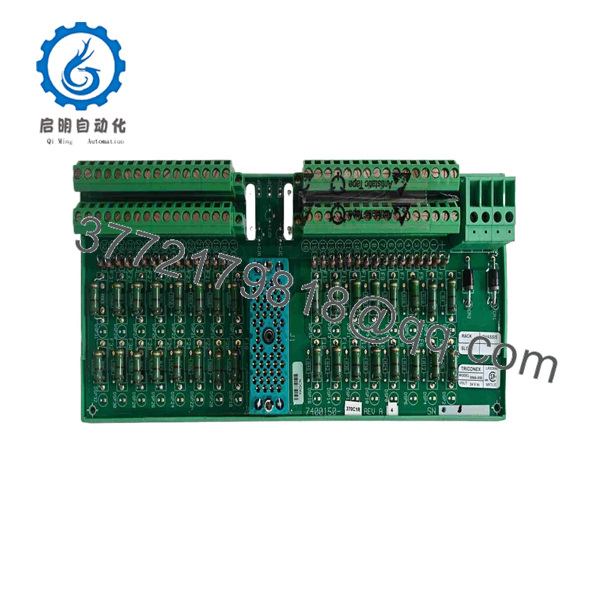
9566-850
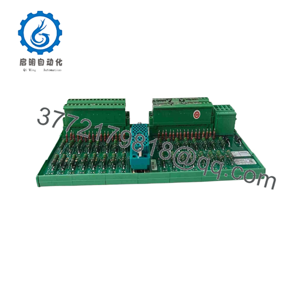
9566-850
Frequently Asked Questions (FAQ)
Q1: What is the TRICONEX 9566-850?
Available supplier catalogs associate the 9566-850 with Triconex communication/interface hardware. However, descriptions are inconsistent, so the exact component type should be verified against the installed hardware and OEM documentation.
Q2: Is 9566-850 a communication card or an I/O termination cable?
This is one of the main identification issues with this part number. One current catalog calls it a Communication Card, while another Triconex product catalog lists 9566-850 as an I/O Termination Cable. Do not purchase solely from a generic online description.
Q3: Is 9566-850 part of the Tricon TMR system?
Yes. The available sources associate the part number with the Triconex/Tricon safety-system ecosystem and TMR-based equipment.
Q4: Can I replace a 9566-850 with another 9566-series part?
No—not without documentation confirming compatibility. 9566-810F and 9566-850 should not be treated as interchangeable simply because their numbers are similar. Current catalogs list them as different components.
Q5: Can the component be hot-swapped?
Do not assume that it can. The correct procedure depends on the specific Tricon chassis, hardware revision, system configuration, and approved maintenance procedure. Follow the applicable Triconex installation documentation.
Q6: What should I send a supplier when ordering 9566-850?
Provide the complete 9566-850 part number, a clear photograph of the nameplate, photographs of both sides of the component, connector photographs, chassis/slot information, and the existing system BOM or drawing. This is especially important because current third-party listings disagree about the component’s exact function.
Q7: Is TRICONEX 9566-850 obsolete?
The sources reviewed do not establish an authoritative OEM lifecycle status for this exact part number. For a legacy Tricon installation, verify lifecycle status directly against the applicable Schneider/Triconex documentation before deciding whether to stock additional units.



