
 WhatsApp: +86 16626708626
 Email:
  Phone: +86 16626708626
Description
Key Technical Specifications
| Parameter | Specification |
| Number of Output Channels | 16 TMR Channels (Points) |
| System Architecture | Triple Modular Redundant (TMR) with Quad Voter switching |
| Nominal Output Voltage | 24 VDC |
| Operating Voltage Range | 15 VDC to 30 VDC (Absolute Max: 33 VDC) |
| Rated Output Current | 3.0 A continuous per point (at switching state); 1.5 A in degraded mode |
| Maximum Surge Current | 4.8 A self-limiting per point |
| Off-State Leakage Current | < 1.0 mA |
| On-State Voltage Drop | < 1.0 VDC at 1.5 A load |
| Loop Scan Time | < 1.0 ms across all 16 channels |
| Isolation Rating | \ge 800 VDC logic-to-bus; \ge 500 VDC functional-to-protective earth |
| Diagnostic Fault Detection | Continuous point-by-point loop testing (detects stuck ON/OFF switches within 500 ms) |
| Safety Integrity Level | Certified SIL 3 (IEC 61508 compliant) |
Product Introduction
The Schneider Electric Invensys Triconex DO3401 (Model 3401) is a 16-channel Triple Modular Redundant (TMR) digital output card engineered exclusively for the Trident Safety Instrumented System (SIS) architecture. Purpose-built for critical process industries—including emergency shutdown (ESD), fire and gas (F&G), and burner management systems (BMS)—the DO3401 executes safe, fault-tolerant control commands to field relays, solenoid valves, and motor trips.
Utilizing Triconex’s patented Quad Voter output circuit, the DO3401 processes commands across three isolated processing legs, combining parallel and series solid-state switches to guarantee a 2-out-of-3 (2oo3) voting mechanism. This architecture prevents single-point field failures: a failed transistor cannot cause a false trip or hold an output stuck ON. Operating on a 24 VDC nominal loop, the DO3401 features hot-swap replacement support, active current limiting, and real-time point diagnostics to maintain maximum uptime in SIL 3 environments.
Quality Control & SOP Inspection Guidelines
Every Triconex DO3401 module undergoes exhaustive verification on our dedicated Trident test rig before entering inventory:
- Inbound Traceability & Visual Inspection:
- Verify OEM part number label, revision codes, serial numbers, and tamper-evident seals against manufacturing records.
- Conduct micro-optical checks on the edge connectors, backplane interface pins, and structural latches for wear, pin deflection, or thermal stress marks.
- Electrical Isolation & Passive Testing:
- Perform 500 VDC Megger testing between field terminals, system logic earth, and protective ground chassis (target requirement: > 100 M\Omega).
- Inspect reverse-voltage protection circuits and measure static resistance profiles across output switching channels.
- Live TMR Chassis & Diagnostic Handshake:
- Slot the DO3401 into a live Triconex Trident backplane.
- Boot the chassis and monitor the power-on self-test (POST) sequence. Verify system communication LEDs,
PASS/FAULTindicators, and channel-level diagnostic updates. - Query the module status via TriStation 1131 software to confirm zero memory errors or channel faults stored in internal registers.
- Dynamic Quad-Voter Load & Fault Injection Test:
- Connect all 16 channels to a 24 VDC inductive load bank.
- Cycle output channels at rated continuous currents (up to 3.0 A per channel) while recording voltage drops (must stay < 1.0 VDC).
- Inject single-leg processor faults to force 2oo3 voting and confirm proper output execution without dropping the field load. Verify automated fault logging responds within 500 ms.
- Hot-Swap & Thermal Run-In:
- Perform hot-swapping under active communications to verify live backplane bus isolation without throwing system glitches.
- Thermal-scan drive transistors during a continuous 24-hour full-load run-in phase.
- Package in anti-static ESD shielding bags, apply QC PASS inspection tags, and log all test metrics to the product archive.
Technical Pitfall & Field Survival Guide
❗ 1. Never Force the Module into the Trident Slot:
The backplane keying slots on Trident chassis prevent incorrect module positioning. If a card resists insertion, stop immediately. Applying excessive insertion force bends the backplane interconnect pins, damaging both the card connector and the backplane bus. Align the card rails precisely before engaging the locking levers.
❗ 2. Verify Field Power Supply Polarity & Voltage Ranges:
The output stage requires an external 24 VDC field power supply wired through the baseplate terminal block. While the module accepts 15 to 30 VDC, an unintended reverse-polarity feed will blow the channel protection paths. Measure your field supply voltage directly at the terminal block before locking the card into place.
❗ 3. High Inductive Load Kickback & External Flyback Diodes:
Although the features internal short-circuit and current-limiting circuits, driving large, unsuppressed 24 VDC solenoids or heavy relay coils creates significant inductive back-EMF spikes. Repeated voltage spikes exceeding 33 VDC will degrade the Quad Voter solid-state switches over time. Always install external flyback diodes (e.g., 1N4007) or transient voltage suppressors (TVS) directly across field inductive coils.
❗ 4. Hot-Swapping Safety Protocol:
The supports live hot-swapping. However, before pulling an active card from the rack, verify that the adjacent redundant slot (or replacement module setup) is fully synced and showing a solid PASS status in TriStation 1131. Pulling a primary card while the secondary card is in a degraded or faulted state will cause an immediate loss of field outputs and trigger a trip on downstream equipment.
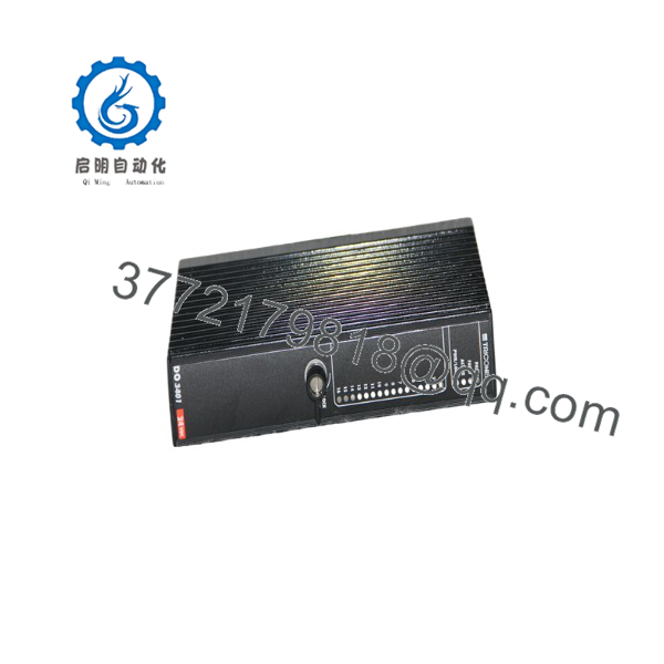
DO3401
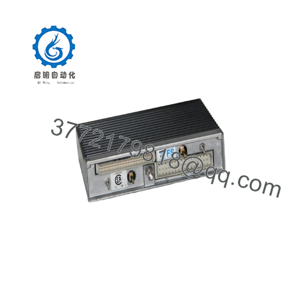
DO3401
Troubleshooting Quick Reference
| Symptom | Possible Cause | Relevance to | Quick Check Method | Recommendation |
FAULT LED solid RED on front panel |
Hardware failure, POST error, or internal voter switch fault | ✅ High | Query diagnostic buffer in TriStation 1131 software for specific error code | If fault persists after cycling module seat, internal voter channel is blown. Replace module. |
| Channel LED illuminated green, but zero field voltage | Blown field fuse on baseplate or missing external 24 VDC supply | ⚠️ Medium | Measure voltage across field terminal block inputs (+24 VDC) | Verify field power supply and check external wiring/fuses on the terminal baseplate. |
LOAD FAULT or Diagnostic alarm active |
Open circuit, field wiring short, or load < 1.0 mA | ✅ High | Measure field load impedance and verify loop continuity with a multimeter | Re-seat terminal block, inspect solenoid coil resistance, or add a bleed resistor for ultra-low power loads. |
| Output stuck in ON state | Quad voter output switch shorted due to high voltage surge | ✅ High | Disconnect module from backplane and measure resistance across output channel pins | Replace the card; send the degraded unit in for component repair. |
| Field load drops intermittently | Field voltage dipping below 15 VDC under surge loads | ❌ Low | Measure field supply voltage under full load using peak-hold multimeter | Increase external 24 VDC power supply sizing or split heavy solenoid loads onto separate power rails. |
Note: If diagnostic logs point to backplane bus timeouts, archive the system diagnostic logs from TriStation 1131 and contact our technical engineering team for analysis.
Frequently Asked Questions (FAQ)
Q: Can I use the module in a standard Tricon v9/v10 rack?
A: No. The is built specifically for the Triconex Trident Safety Instrumented System (SIS) architecture. Full-size Tricon chassis use different form-factor digital output modules (such as Model 3604E or 3625). Always verify your rack type before ordering.
Q: Does the support hot-swapping while the plant is actively running?
A: Yes. The supports online hot-swapping. When paired with a redundant slot configuration on the Trident baseplate, you can pull a faulted module and insert a replacement without interrupting system operation or shutting down field actuators.
Q: What is the difference between a standard PLC output card and the TMR output module?
A: Standard PLC cards use single-transistor or relay outputs, meaning a shorted component leaves the output stuck ON or OFF. The uses Triple Modular Redundancy (TMR) with a Quad Voter circuit. It processes commands across three independent legs, allowing the system to detect component faults, issue system warnings, and maintain control integrity even if an internal component fails.
Q: Do I need to re-program the system when installing a replacement card?
A: No. The control logic resides in the Trident Main Processor modules. When you insert a replacement card into an existing slot, the main processors automatically recognize the module, verify its hardware ID, run background diagnostic checks, and resume output control.
Q: What warranty coverage do you provide on New Surplus and Refurbished cards?
A: Every unit—whether New Surplus or fully reconditioned—comes backed by our 1-year replacement warranty. If a module fails internal diagnostics or trips a hardware fault during standard operation within 12 months of purchase, we dispatch an advance replacement module directly from active stock to prevent plant downtime.



