
 WhatsApp: +86 16626708626
 Email:
  Phone: +86 16626708626
Description
Key Technical Specifications
| Parameter | Value / Specification |
| Manufacturer | Triconex (Schneider Electric / Invensys) |
| Part Number | HD8311 (Sub-variants: 8311, 8311N) |
| Architecture | Triple Modular Redundant (TMR) |
| Input Channels | 32 Isolated Digital Inputs |
| Nominal Voltage | 24 V DC |
| Operating Voltage Range | 18 V DC to 32 V DC |
| Isolation | Channel-to-Bus: 1500 V RMS; Optical Isolation |
| System Compatibility | Tricon V9, V10, and high-density expansion chassis |
| Power Dissipation | ~5 W (nominal) |
| Operating Temperature | 0 °C to +60 °C (32 °F to 140 °F) |
| Storage Temperature | −40 °C to +75 °C (−40 °F to 167 °F) |
| Relative Humidity | 5% to 95% non-condensing |
Product Introduction & Supply Chain Strategy
The TRICONEX HD8311 is a 32-channel high-density digital input module engineered for fault-tolerant Safety Instrumented Systems (SIS). Operating within a Triple Modular Redundant (TMR) framework, it processes emergency shutdown (ESD), fire and gas monitoring, and burner management system (BMS) field signals with voting logic that guarantees zero single points of failure.
Maintaining a New Surplus TRICONEX HD8311 module on-site provides an indispensable safety layer for process plant operations. OEM lead times for high-density safety modules often exceed standard supply schedules, creating severe risks of extended process shutdowns during hardware faults. Sourcing genuine New Surplus ensures original dielectric isolation ratings, unaged optical couplers, and pristine backplane pin structures—eliminating the hidden thermal stress and erratic switching behaviors inherent to second-hand or refurbished safety cards.
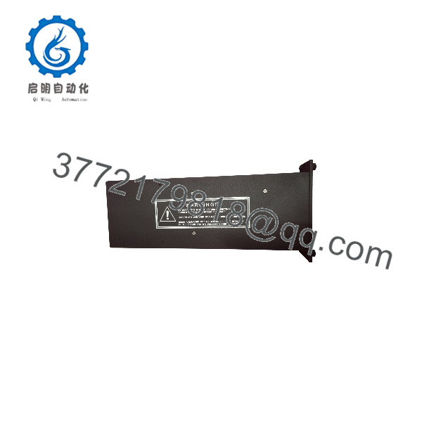
HD8311
HD8311
Installation & Configuration Guide
Stage 1: Pre-Installation (Prep & Safety)
- Execute full Lock-Out/Tag-Out (LOTO) protocols on field loop power feeds and local panel power distribution blocks.
- Put on a grounded wrist strap connected to cabinet earth to prevent ESD damage to sensitive input logic buffers.
- Inspect the module chassis and rear connector pins for alignment, verifying keying pins match the designated rack slot.
Stage 2: Removal
- Disconnect the field wiring arm or unlatch the external termination module (ETM) cable connector attached to the module face.
- Unthread top and bottom retaining screws securing the card to the Tricon I/O slot frame.
- Slide the existing module straight out along its guide tracks without tilting to prevent bending adjacent backplane pins. Immediately store it in an static-shielded container.
Stage 3: Installation (Clone & Seat)
- Unpack the TRICONEX HD8311 from its original anti-static packaging.
- Align the top and bottom card edges with the designated cabinet guide rails.
- Slide the module into the slot until the backplane connectors engage firmly. Press the faceplate flush and tighten the upper and lower mounting screws.
- Re-attach the ETM interface cable or terminal wiring assembly securely.
Stage 4: Power-On & Testing
- Re-energize the 24 V DC field loop power.
- Check front panel LED status: verify the PASS LED is solid green, and confirm FAULT or ALM indicators remain unlit.
- Monitor system diagnostics via TriStation 1131 software to ensure all 32 channels register correct signal states (ON/OFF) during loop verification tests.
Firmware/Software Versions & Upgrade Notes
- TriStation Compatibility: The HD8311 requires appropriate module definitions in TriStation 1131 (Version 4.x or later) corresponding to your main processor firmware.
- TMR Voting Logic: Ensure that all three redundant channels on the HD8311 synchronize correctly with the Main Processor (MP) modules upon card insertion.
- Hardware Revisions: Verify board revision suffixes (e.g., vs 8311N) to guarantee compatibility with your backplane termination panels and active ETM cables.
- Firmware Warning: Do not alter system software configuration files while the safety system is actively protecting live processes. Perform module online swaps strictly according to Triconex hot-spare insertion procedures.
Frequently Asked Questions (FAQ)
Q: How do I know this TRICONEX unit is genuine New Surplus and not a pulled or repaired card?
A: Every unit we offer is 100% Brand New Surplus. It comes in original factory protective packaging, featuring unblemished edge connectors, clean mounting hardware, original serial tags, and zero evidence of prior backplane insertion. It has never been installed in a live plant environment or subjected to repair work.
Q: Why is buying New Surplus essential for safety-critical components like Triconex?
A: Safety systems depend on predictable component behavior. Refurbished safety boards often contain aged optocouplers and capacitors that degrade under continuous duty cycles, causing false trips or, worse, failing to register an active fault. New Surplus provides factory-original component integrity and a 10–15 year service life.
Q: Can the TRICONEX module be hot-swapped while the process is online?
A: Yes. Triconex chassis architectures support online hot-swapping of I/O modules when installed in redundant dual-slot configurations or following standard hot-spare procedures defined in the Triconex System Safety Manual.
Q: What is the main difference between standard digital input cards and the ?
A: The is a high-density variant providing 32 isolated channel inputs per slot, allowing higher I/O channel packing per chassis while maintaining full TMR diagnostic isolation and channel-to-bus protection.
Q: Does the card retain channel configuration parameters if power is lost?
A: Channel mapping and voting logic are stored in the Tricon Main Processors (MP) and downloaded to the upon initial handshake. The module relies on the system’s active software configuration to set field channel behaviors.
Q: What warranty is provided with this New Surplus module?
A: We back this module with a full 1-Year Warranty. Each unit is visually and electrically inspected prior to dispatch.



