
 WhatsApp: +86 16626708626
 Email:
  Phone: +86 16626708626
Description
Key Technical Specifications
| Parameter | AI-7021 |
|---|---|
| Manufacturer | UDIAN / Yudian |
| Model | AI-7021 |
| Function | Dual temperature transmitter / signal isolator |
| Number of Channels | 2 |
| Thermocouple Inputs | K, S, E, J, B, N, T, WRe5-WRe26 |
| RTD Inputs | Pt100, Cu50 |
| Voltage Inputs | 0–20 mV, 0–60 mV, 0–75 mV, 0–100 mV, 0–1 V, 0.2–1 V |
| Current Inputs | 0–20 mA, 4–20 mA |
| Analog Outputs | 2 isolated current outputs |
| Output Range | 0–20 mA / 4–20 mA |
| Output Adjustment | Digitally programmable |
| Supply Options | 24 VAC/DC or 100–240 VAC |
| Isolation | ≥2,300 VDC power-to-I/O; ≥200 VDC input-to-output |
| Power Consumption | ≤3 W |
| Mounting | DIN rail |
| Width | 22.5 mm |
| Operating Temperature | -10 to +60 °C |
| Operating Humidity | 0–90% RH |
The AI-7021 uses independently configurable input channels and digital filtering. Thermocouple inputs include automatic reference-junction compensation, while the retransmission range can be defined through configuration parameters.
The manufacturer’s documentation specifies that the two outputs can operate as independent retransmission channels. A splitter mode is also available, allowing a single input to be assigned to dual outputs under the appropriate configuration.
Product Introduction
The UDIAN AI-7021 is a compact, two-channel temperature transmitter and signal isolator intended for industrial measurement and control panels. Each channel can accept a configurable temperature or analog signal and retransmit it through an isolated current output. The device supports thermocouples, RTDs, millivolt signals, and current inputs.
Its 22.5 mm DIN-rail width allows two independent signal-conditioning channels to occupy relatively little cabinet space. Digital filtering, programmable scaling, and isolated 4–20 mA / 0–20 mA retransmission make the AI-7021 suitable for interfacing field sensors with PLC, DCS, data-acquisition, and monitoring systems.
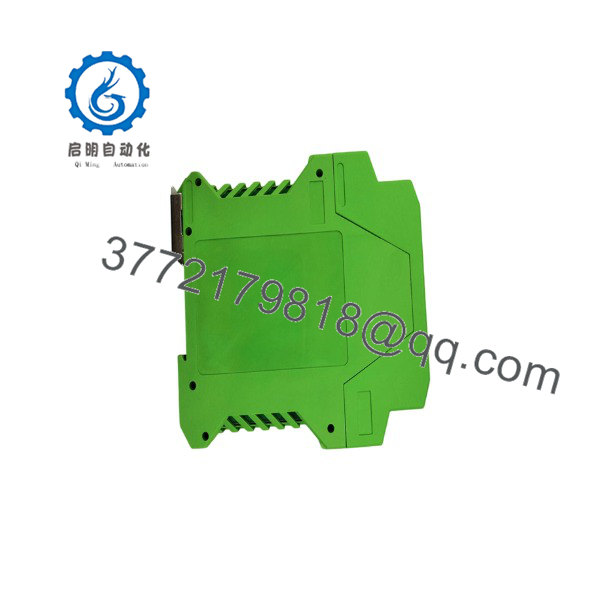
AI-7021
Installation & Configuration Guide
Stage 1 — Pre-Installation Preparation | ~5 minutes
- Isolate the associated control circuit using the site’s lockout/tagout procedure.
- Verify the exact AI-7021 power-supply version before wiring.
- Photograph the existing terminal arrangement.
- Record the input sensor type and measurement range.
- Record the required analog output range, such as 4–20 mA.
- Prepare an ESD strap, multimeter, screwdriver, wire labels, and the original wiring documentation.
⚠️ Do not assume every AI-7021 has the same power-input configuration. Check the nameplate and supplied wiring diagram.
Stage 2 — Remove the Existing Module | ~5 minutes
- Confirm power is removed.
- Label IN1, IN2, OUT1, OUT2, and power conductors.
- Disconnect the field wiring.
- Release the DIN-rail retaining mechanism.
- Remove the existing module.
- Inspect the wiring for damaged insulation or loose terminals.
The current AI-7021 documentation identifies terminals 1–2 for power and terminals 5–6 and 7–8 for the two current retransmission outputs. However, special-order or upgraded versions may use a different wiring diagram, so the documentation supplied with the actual unit takes precedence.
Stage 3 — Install and Configure | ~5–10 minutes
- Mount the AI-7021 securely on the DIN rail.
- Connect the specified power supply.
- Connect the first field sensor to IN1.
- Connect the second sensor to IN2, if required.
- Wire OUT1 and OUT2 to the PLC/DCS analog input channels.
- Configure the input type for each channel.
- Set the required scale-low and scale-high values.
- Set the desired output range.
- Configure digital filtering if required.
The AI-7021 uses programmable parameters rather than mechanical potentiometers for output adjustment. The instrument’s 1394 socket is intended specifically for the manufacturer’s programming device and should not be treated as a general-purpose 1394 interface.
Stage 4 — Power-On & Testing | ~10–15 minutes
- Check power polarity where applicable.
- Verify there are no shorts between field terminals.
- Apply power.
- Confirm the display and channel indicators behave normally.
- Inject or apply a known input signal.
- Measure OUT1 and OUT2 with a calibrated multimeter.
- Confirm the PLC/DCS receives the expected engineering value.
- Check the entire operating range if the application is safety- or process-critical.
- Record the final parameter configuration.
For a 4–20 mA application, verify both the zero point and span rather than checking only the nominal midpoint.
Frequently Asked Questions (FAQ)
What is the UDIAN AI-7021 used for?
It is used as a two-channel temperature transmitter or signal isolator. It accepts configurable temperature and analog signals and produces two isolated current outputs for connection to control or monitoring equipment.
What sensors can the AI-7021 accept?
Supported inputs include K, S, E, J, B, N, T and WRe5-WRe26 thermocouples, Pt100 and Cu50 RTDs, as well as several mV, voltage, and current ranges.
Does the AI-7021 provide 4–20 mA output?
Yes. The two retransmission outputs can be configured for 4–20 mA or 0–20 mA, with the engineering scale freely defined through the instrument parameters.
Can the two AI-7021 channels be configured independently?
Yes. Each input channel has its own input and scaling parameters. Digital filtering can also be configured for the individual channels.
What power supply does the AI-7021 require?
The AI-7021 documentation identifies versions supporting 24 VAC/DC and versions supporting 100–240 VAC. Confirm the exact power-input marking on the unit before connecting power.
Can the AI-7021 replace another temperature transmitter directly?
Only after checking the complete electrical and mechanical requirements. Verify input type, sensor range, output configuration, power supply, terminal assignment, isolation requirements, and DIN-rail installation dimensions. A similar 4–20 mA transmitter is not automatically an electrical substitute.
What should be specified on an RFQ?
Provide UDIAN AI-7021, the complete nameplate/version information, power-supply type, required input sensors, output range, quantity, and required condition. If replacing an installed unit, include a photograph of the nameplate and terminal layout. This is particularly important because the AI-7021 has multiple input and power configurations.



