
 WhatsApp: +86 16626708626
 Email:
  Phone: +86 16626708626
Description
3. Key Technical Specifications
| Parameter | Value |
|---|---|
| Manufacturer | Valmet Automation |
| Model Number | A413001 |
| Known Revision | Rev. 10 |
| Product Type | CPU Central Processor Module |
| Function | Main Controller Processing Unit |
| Installation Method | Rack Mounted |
| Application | PLC / DCS Control System |
| System Generation | Legacy Valmet Automation Platform |
| Communication Role | Controller and rack management |
| Hardware Category | CPU Board |
| Availability Status | Obsolete / Surplus Market |
| Replacement Strategy | Verify hardware revision and firmware before installation |
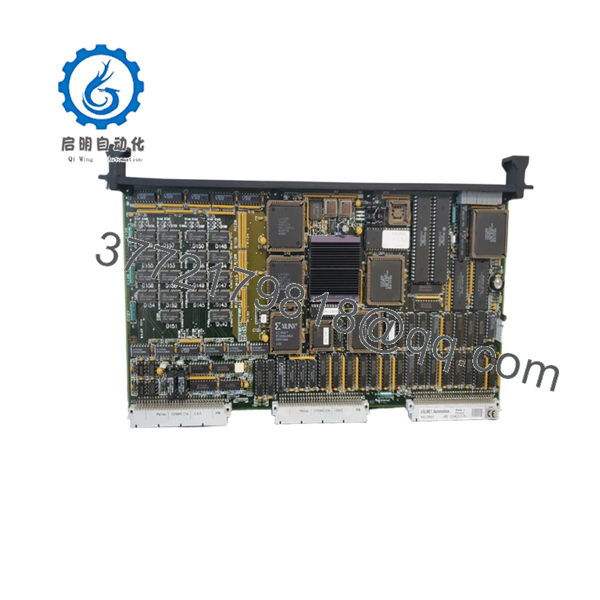
4. Product Introduction
The VALMET A413001 is a CPU Central Processor Module used as the primary processing element in legacy Valmet automation and control systems. The module executes control logic, manages communications, and coordinates rack-level operations within the installed PLC or DCS architecture.
In operating facilities where the original Valmet platform remains in service, replacing a failed A413001 can restore operation without the engineering effort and downtime associated with a full migration project. Before installation, engineers should verify hardware revision, firmware level, and backplane compatibility.

- A413001
5. Installation & Configuration Guide
Stage 1: Pre-Installation Preparation (10–15 Minutes)
⚠️ Safety First
- Notify production personnel of the planned outage.
- Place the process in a safe operating state.
- Apply Lock-Out/Tag-Out procedures.
- Remove control power.
- Wait at least 5 minutes for internal capacitors to discharge.
Tools Required
- ESD wrist strap
- PH1 screwdriver
- Fluke 115 multimeter
- Wire labels
- Smartphone for documentation
- Flashlight
Data Backup
- Export controller configuration files.
- Backup application logic.
- Record network parameters and node addresses.
- Photograph:
- CPU module
- DIP switches
- Jumper settings
- Rack slot position
- Terminal wiring
⚠️ Critical
Document the installed firmware revision before removing the existing CPU.
I’ve seen projects lose nearly two days because a replacement processor arrived with a different firmware revision than the running plant system.
Stage 2: Removing the Old Module (5–10 Minutes)
- Open the cabinet and remove protective covers.
- Label all wiring and communication cables.
- Disconnect connectors carefully.
- Release retaining clips or rack locks.
- Pull the module straight outward.
Inspect the Rack
Check for:
- Bent backplane pins
- Corrosion
- Dust buildup
- Loose connectors
⚠️ Important
Keep the original CPU available until startup testing is complete.
Stage 3: Installing the New Module (10 Minutes)
Step 1 – ESD Protection
- Connect the wrist strap.
- Work only on an ESD-safe surface.
Step 2 – Configuration Clone (CRUCIAL)
- Compare:
- Model number
- Revision level
- Hardware identification
- Replicate:
- DIP switches
- Jumpers
- Node addressing
- Bus termination settings
❗ This is the most common rookie mistake, but it happens constantly. Take a picture before you pull it. I can’t stress this enough.
Step 3 – Install CPU
- Align module guides.
- Insert evenly into the rack.
- Press until fully seated.
- Verify locking mechanisms engage.
Step 4 – Reconnect Wiring
- Reinstall all communication connectors.
- Verify cable routing.
- Check shield grounding.
Self-Checklist
- Correct model installed
- DIP settings match
- Wiring secured
- Module fully seated
- Locking tabs engaged
Stage 4: Power-On & Testing (15–20 Minutes)
Pre-Power Checks
Using a multimeter:
- Verify 24 V supply integrity.
- Check for shorts.
- Confirm ground continuity.
Power-Up Sequence
- Energize the rack only.
- Observe CPU startup LEDs.
- Verify normal boot sequence.
- Connect engineering software.
- Confirm CPU recognition.
- Verify firmware revision.
- Restore configuration if required.
- Test communications.
- Simulate I/O operation.
Functional Verification
- CPU diagnostics clear
- Communication links active
- No watchdog alarms
- I/O responding correctly
- Process values updating normally
⚠️ Troubleshooting Note
- Solid fault LED → firmware mismatch or hardware fault.
- Communication timeout → verify addressing and network settings.
- CPU boots but process remains offline → verify configuration restoration and rack addressing.
6. Frequently Asked Questions (FAQ)
Q1. Can I hot-swap the VALMET A413001 CPU?
No.
As a CPU module, the A413001 is typically the controller’s primary processing component. Removing it under power can stop communications, generate rack faults, and potentially damage hardware. Power down the system before replacement.
Q2. Is the VALMET A413001 obsolete?
Yes.
The A413001 belongs to an older generation of Valmet automation hardware. Most currently available units originate from surplus inventories, plant decommissioning projects, or specialist automation suppliers.
Q3. What should I verify before ordering?
Verify:
- A413001 part number
- Hardware revision
- Firmware version
- Rack type
- Backplane compatibility
- Existing communication architecture
Do not assume all revisions are interchangeable.
Q4. Will I lose my program if I replace the CPU?
Possibly.
That depends on where the application is stored.
Some legacy systems store configuration within the CPU memory, while others maintain backups on engineering workstations or removable media. Always create a complete backup before removal.
Q5. What is the most common installation mistake?
DIP switch and jumper configuration.
I’ve watched technicians install a perfectly functional replacement CPU only to spend hours troubleshooting because the node address or communication settings were left at factory defaults.
Take photographs before removal.
Q6. Why can identical A413001 modules have different prices?
Three factors usually drive pricing:
- Condition (New Surplus vs Refurbished)
- Traceability documentation
- Functional testing performed before shipment
A fully tested module with a documented load test and warranty generally costs more than an untested warehouse spare.
Q7. What quality-control process should be performed before shipment?
A professional supplier should complete the following process:
Inbound Inspection & Traceability
- OEM label verification
- Serial number recording
- Anti-counterfeit inspection
- Visual examination for:
- Corrosion
- Scratches
- Rework marks
- UV discoloration
Functional Testing
- Installation into a compatible Valmet test rack
- Power-on verification
- Communication handshake testing
- CPU diagnostic testing
- Continuous operation for at least 24 hours
- Test report generation
Electrical Testing
- 500 V Megger insulation resistance test (>10 MΩ)
- Ground continuity verification
- Hipot testing where applicable
Firmware Verification
- Record firmware revision
- Document hardware revision
- Photograph DIP switch and jumper settings
Final QC & Packaging
- QC inspector sign-off
- ESD-safe packaging
- Bubble wrap protection
- Heavy-duty corrugated carton
- QC Passed label with inspection date
Test photos and videos should be available upon request.
Common Replacement Pitfalls
❗ Firmware Revision Mismatch
I’ve seen a replacement CPU arrive with newer firmware than the installed rack components. The result was two days of communication faults before anyone checked the firmware revision.
Document the existing version before ordering.
❗ DIP Switch Misconfiguration
Factory defaults rarely match plant requirements.
Take photographs and duplicate every setting.
❗ Terminal and Connector Differences
Even similar revisions can have connector changes.
Always compare manuals and wiring diagrams rather than wiring from memory.
❗ Power Consumption Oversight
Verify total rack power requirements and maintain at least a 20% power supply margin.
Legacy power supplies often operate very close to their limits.
❗ Electrostatic Discharge (ESD)
I once watched a technician handle a processor board during winter maintenance without an ESD strap. The board failed immediately during startup.
Use a grounded wrist strap and ESD-safe work surface every time.
Keep these checks in mind and you’ll save yourself 90% of typical rework time.


